Projekte
Projects
Labornetzteil aus PC Netzteil - Eigenbau
Laboratory power supply from PC power supply - DIY
01.2021
Überblick
Overview
Geplantes Budget
planed budget
Fortschritt
progress
Design
Prepare
Build
Test
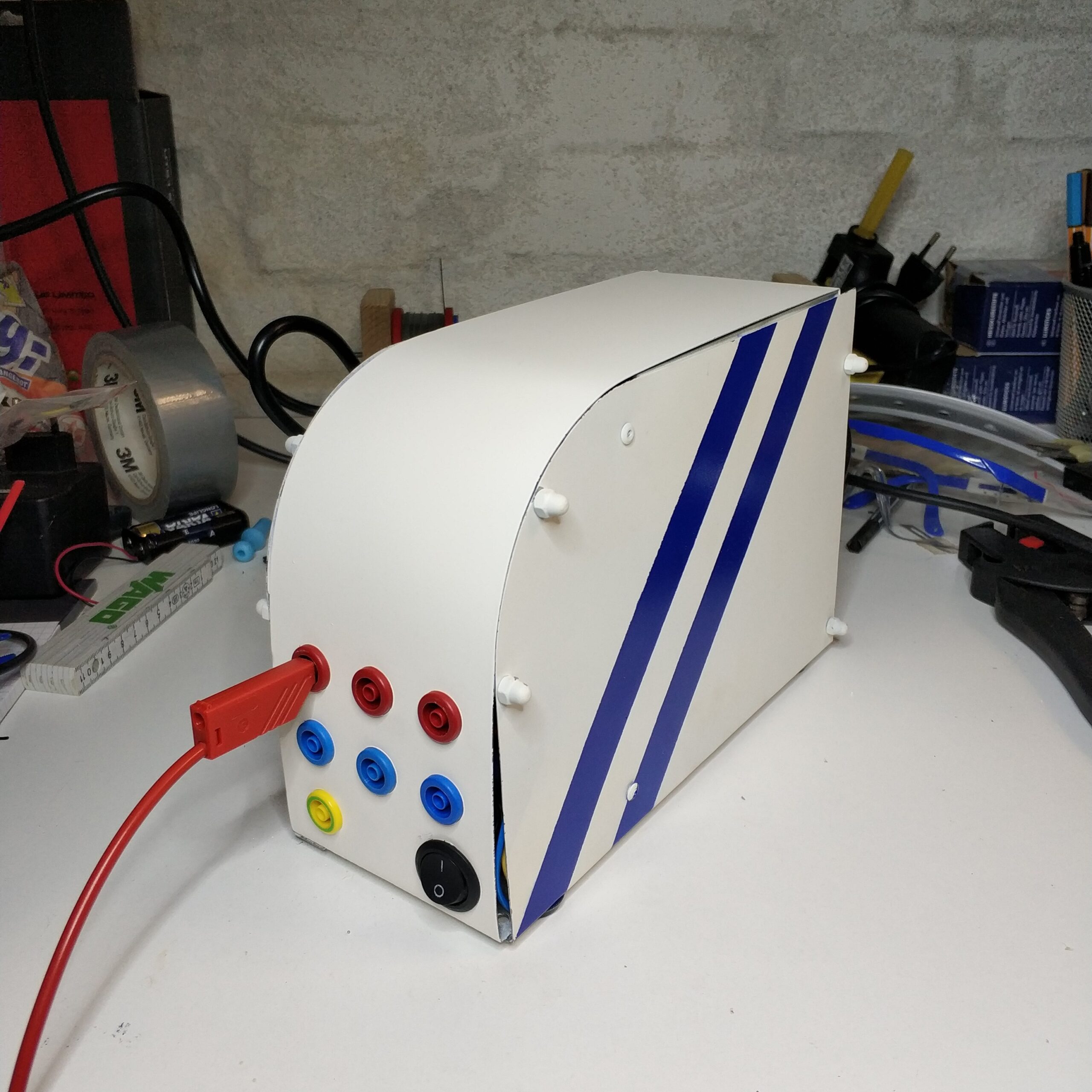
Done!
Maschienen und Werkzeuge
Machines and tools


Einleitung
Für ein kommendes Projekt brauche ich eine Gleichstromquelle. Hierfür habe ich ein altes Projekt herausgekramt, dass seit guten 5 Jahren brach lag. Wie der Titel verrät war damals der Plan ein alten PC Netzteil in ein Labornetzteil umzubauen. Um dem ganzen ein bisschen mehr Eleganz und Labor Charakter zu verpassen habe ich damals angefangen ein Gehäuse zu bauen. Die Seitenwände sind fertig die Frontabdekung allerdings nicht. Da ich jetzt eine Anwendung hatte und auch besser ausgestattet bin, habe ich mich wieder auf das Projekt gestürzt und es dann an einem Wochenende in einen funktionsfähigen Status gebracht. Heute würde ich einige Dinge anders machen aber Damals hatte ich praktisch nur eine Säge, ein elektrisches Multitool und Sprühlack.
Warum ein PC Netzteil?
Günstige Labornetzteile fangen schon bei 30€ an warum sollte man also eine DIY variante machen? Zum eine lernt man beim Bau einiges und solange man nicht anfängt das PC Netzteil aufzuschrauben ist man auch recht sicher unterwegs, was die elektrische Spannung an geht. Zum anderen kann man so zumindest etwas den Elektroschrott reduzieren. Denn oft kann man die PC Netzteile sogar umsonst abgreifen wenn ein alter PC entsorgt werden soll. Das schont also Umwelt und den Geldbeutel.
Am interessantesten am PC Netzeil sind aber eigentlich die möglichen Spannungen mit denen man arbeiten kann. Das PC Netzteil kann eine Spannung bis 24V erzeugen. Um so eine Spannung bei gekauften Labornetzteilen zu finden muss man dann damals gute 80€ ausgeben. Heute kann man schon welche ab 50€ wo man dann auch den Strom limitieren kann, was bei dem PC Netzteil so ohne weiteres nicht geht. Heute würde ich vermutlich auch ein Netzteil kaufen, wegen der erwähnten regelbaren Strombegrenzung und der regelbaren Spannung. Was der Unterschied zum PC Netzteil ist erkläre ich unten.
Introduction
For an upcoming project, I need a DC power source. For this I dug out an old project that had been idle for a good 5 years. As the title suggests, the plan was to convert an old PC power supply into a laboratory power supply. In order to give the whole thing a little more elegance and laboratory character, I started to build a case back then. The side walls are finished, but the front cover is not. Since I now had an application and am better equipped, I threw myself back on the project and then got it into a functional state over a weekend. Today I would do a few things differently, but at that time I basically only had a saw, an electric multitool and spray paint.
Why a PC power supply?
Cheap laboratory power supplies start at 30€, so why should you do a DIY variant? On the one hand, you learn a lot during construction and as long as you don’t start to unscrew the PC power supply, you are also quite safe on the road with regard to the electrical voltage. On the other hand, you can at least reduce e-waste somewhat. Because often you can even tap the PC power supply for free if an old PC is to be disposed of. So that saves the environment and your wallet.
The most interesting thing about the PC power supply are actually the possible voltages with which you can work. The PC power supply can generate a voltage of up to 24V. In order to find such a voltage with purchased laboratory power supplies, you then have to spend a good 80€. Today you can get some from 50€ where you can also limit the current, which is not easy with the PC power supply. Today I would probably also buy a power supply, because of the mentioned adjustable current limit and the adjustable voltage. I explain below what the difference to the PC power supply is.
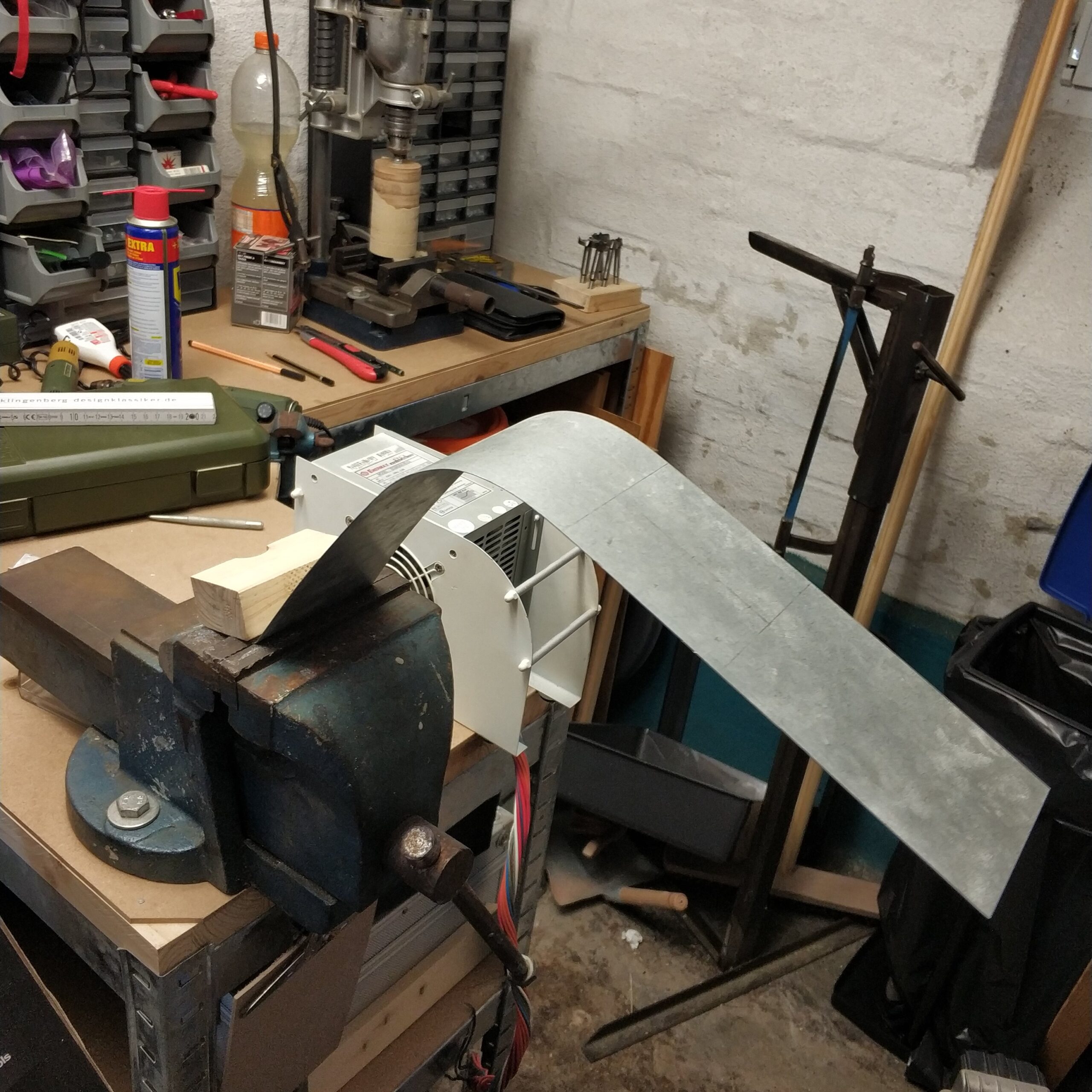
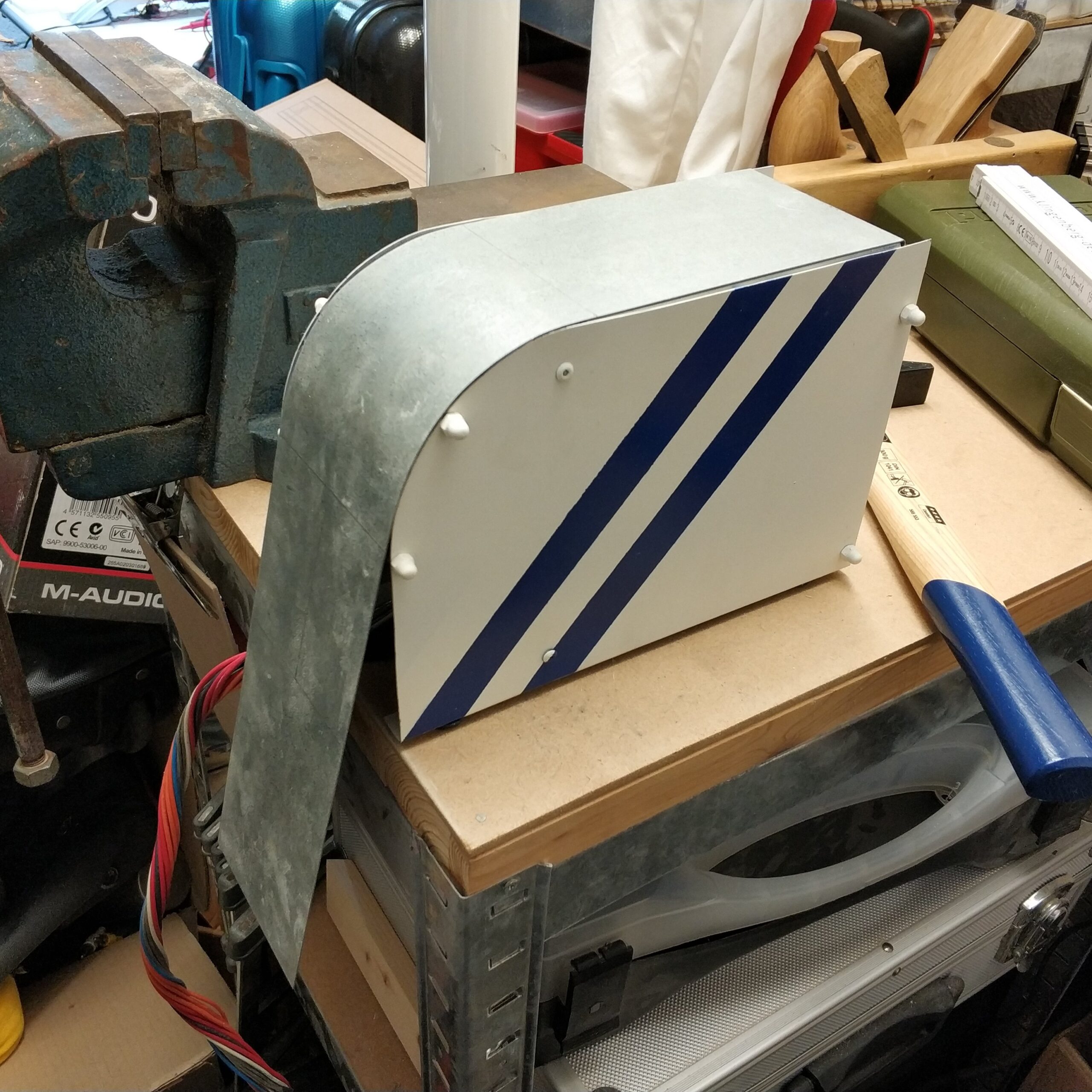
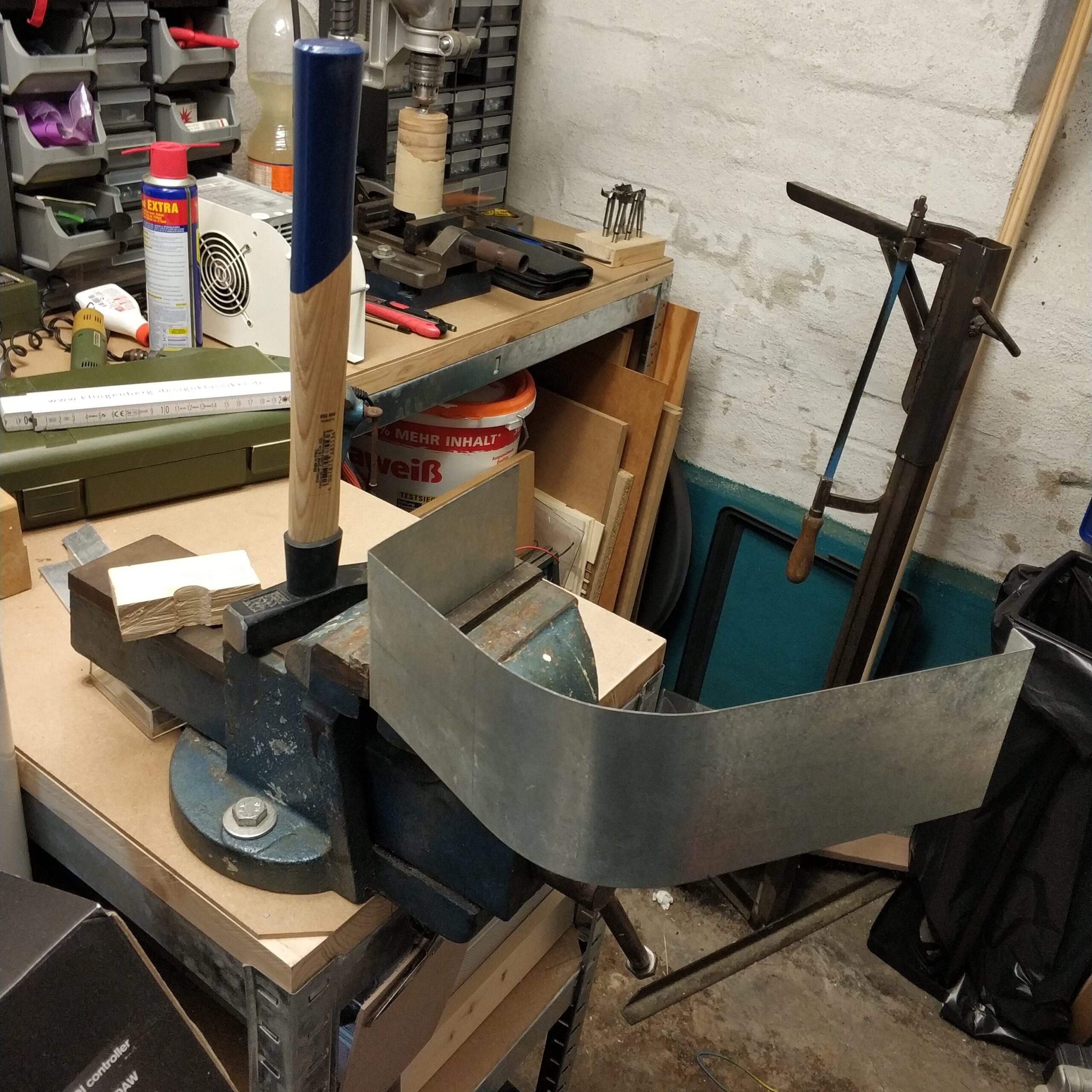
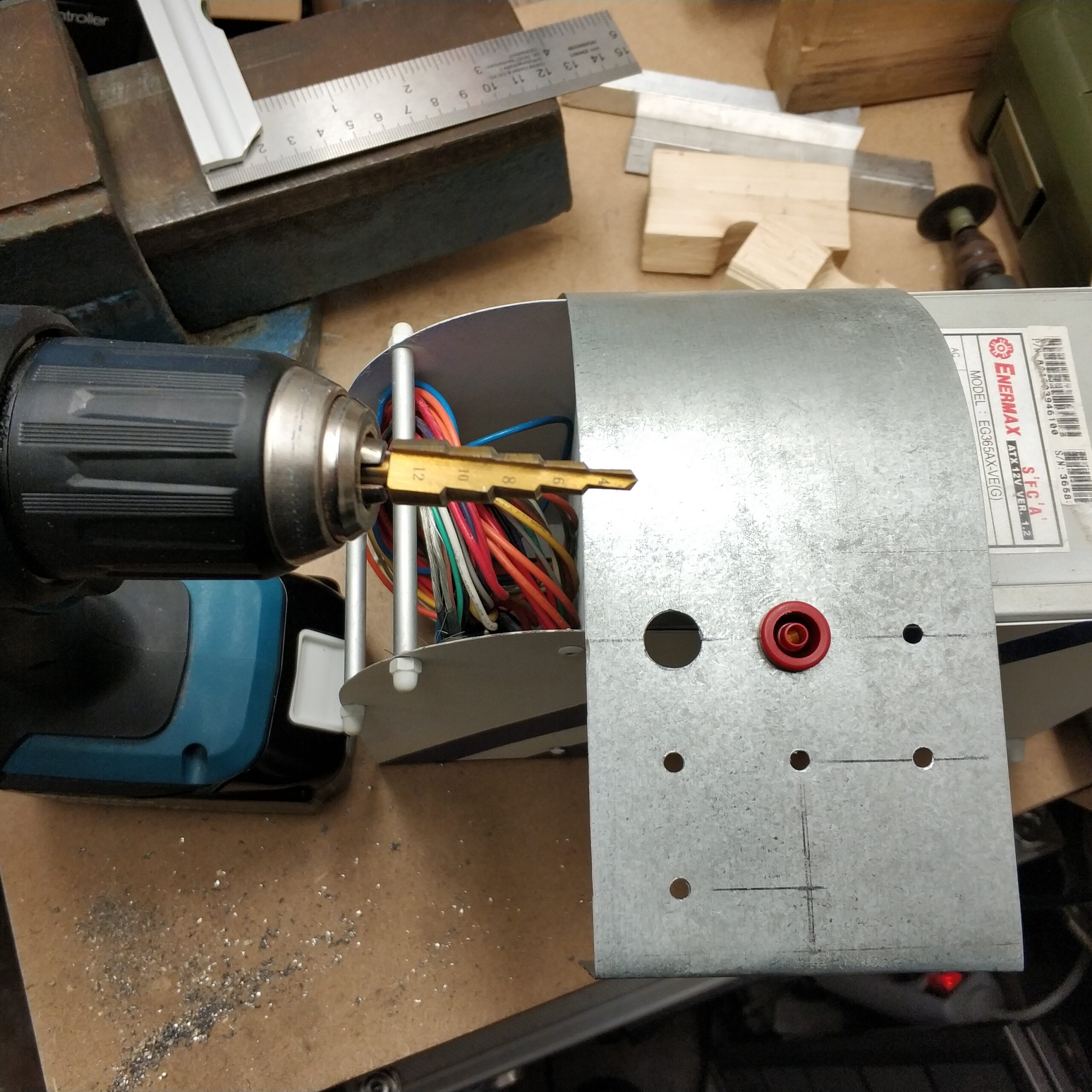
Blech biegen und Löcher bohren
Damals hatte ich es noch geschafft ein verzinktes Blech in die Richtige Breite zu schneiden. Das Projekt wurde dann aber auf Eis gelegt weil ich keine gute Möglichkeit sah, dass Frontblech halbwegs adäquat zu biegen. Perfekt wäre eine dieser 3 in 1 Blech Bearbeitungsstationen die aber damals wie heute sich in der Anschaffung nicht lohnen. Aber mit dem Schraubstock und der Blechbiege Erfahrung aus dem Bluetooth Kopfhörer Projekt habe ich mir das ganze jetzt zugetraut.
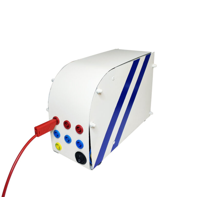
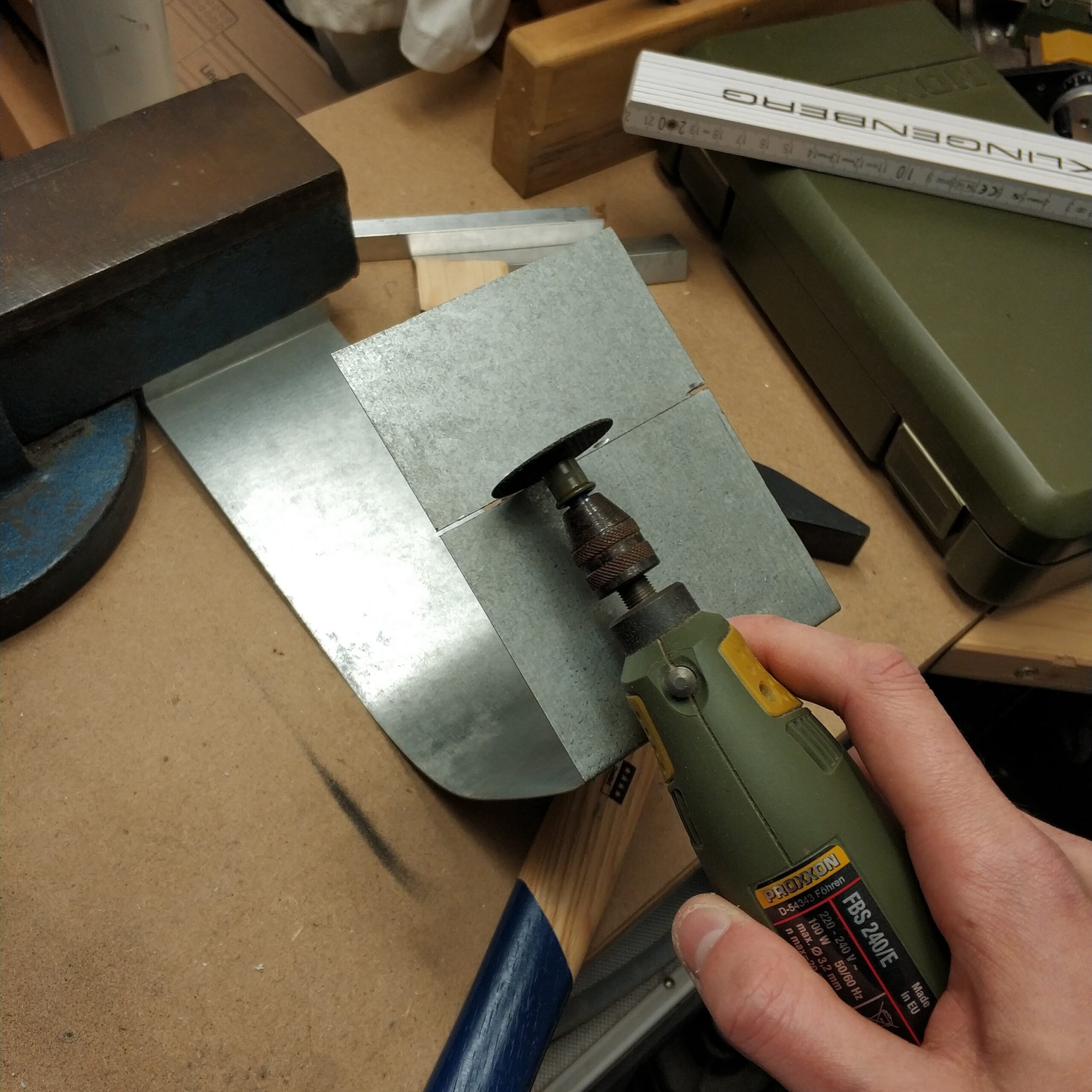
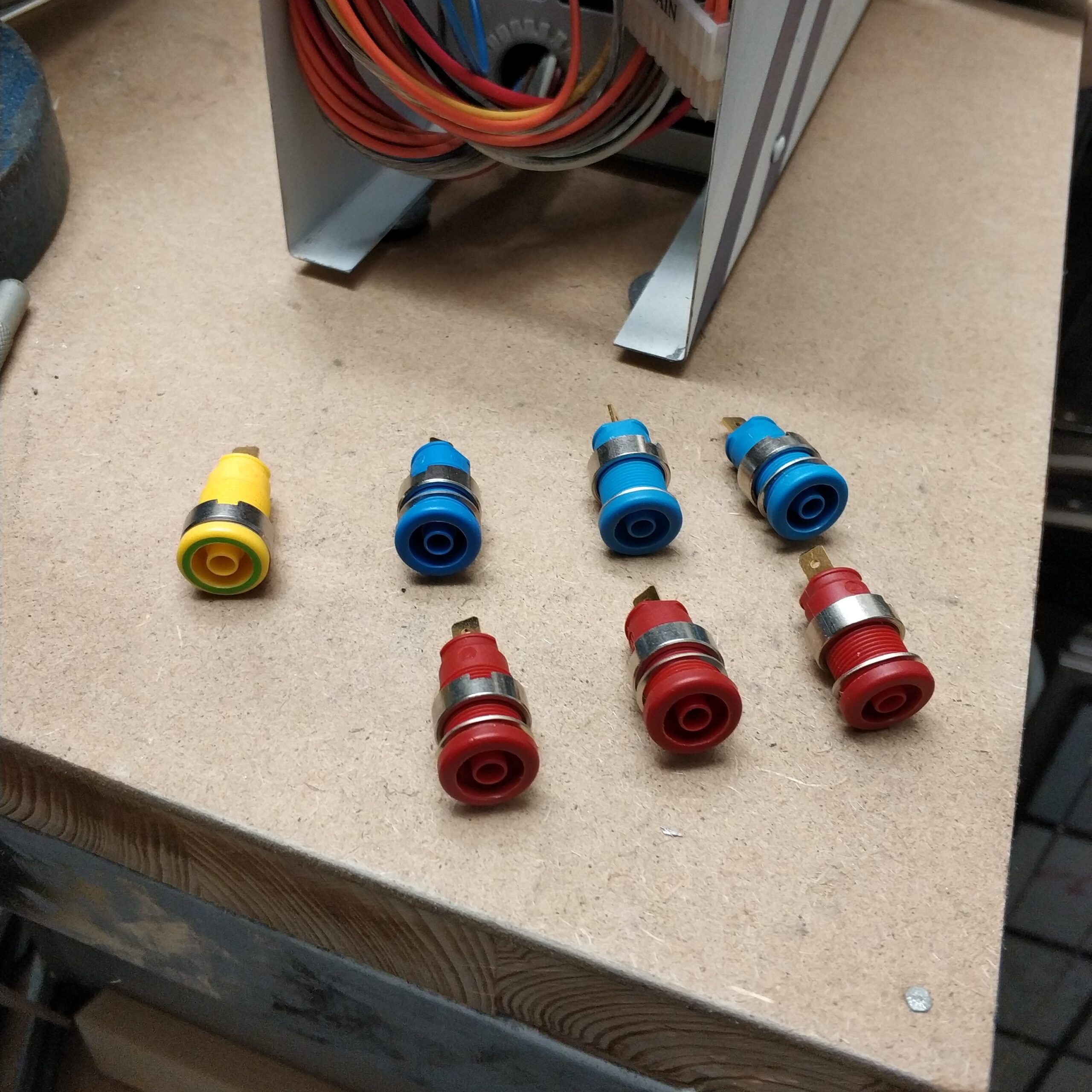
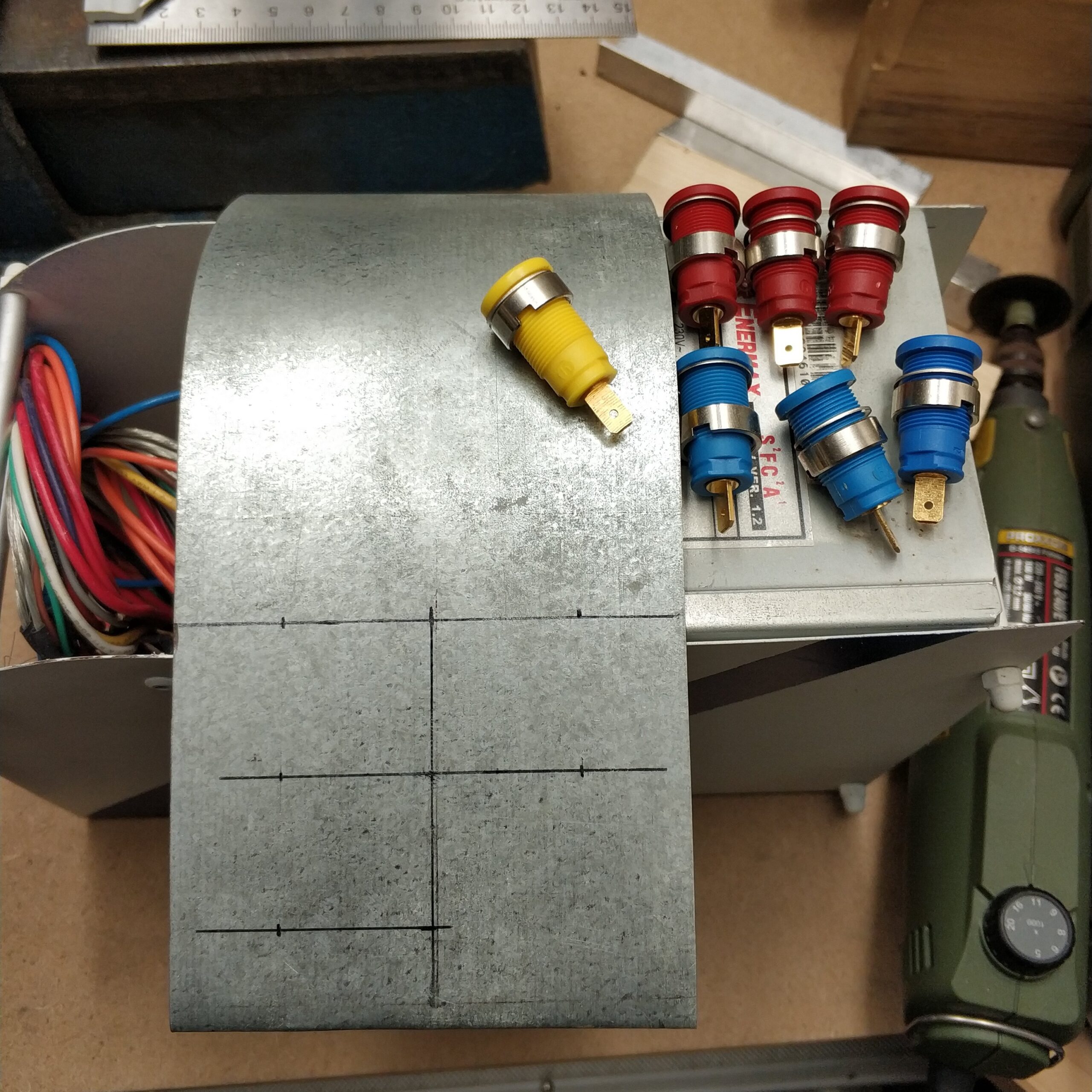
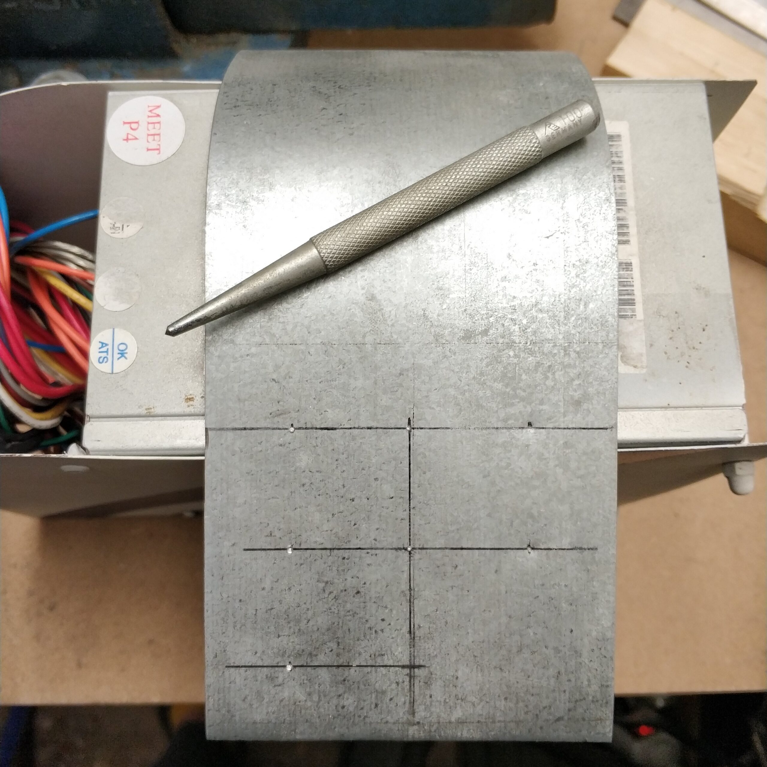
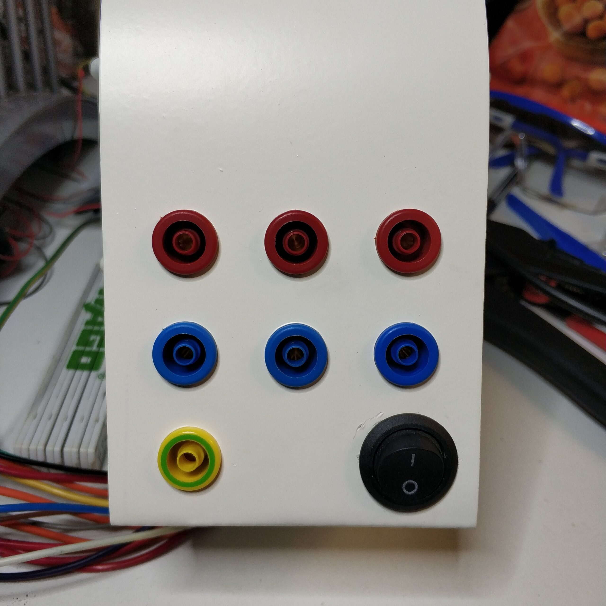
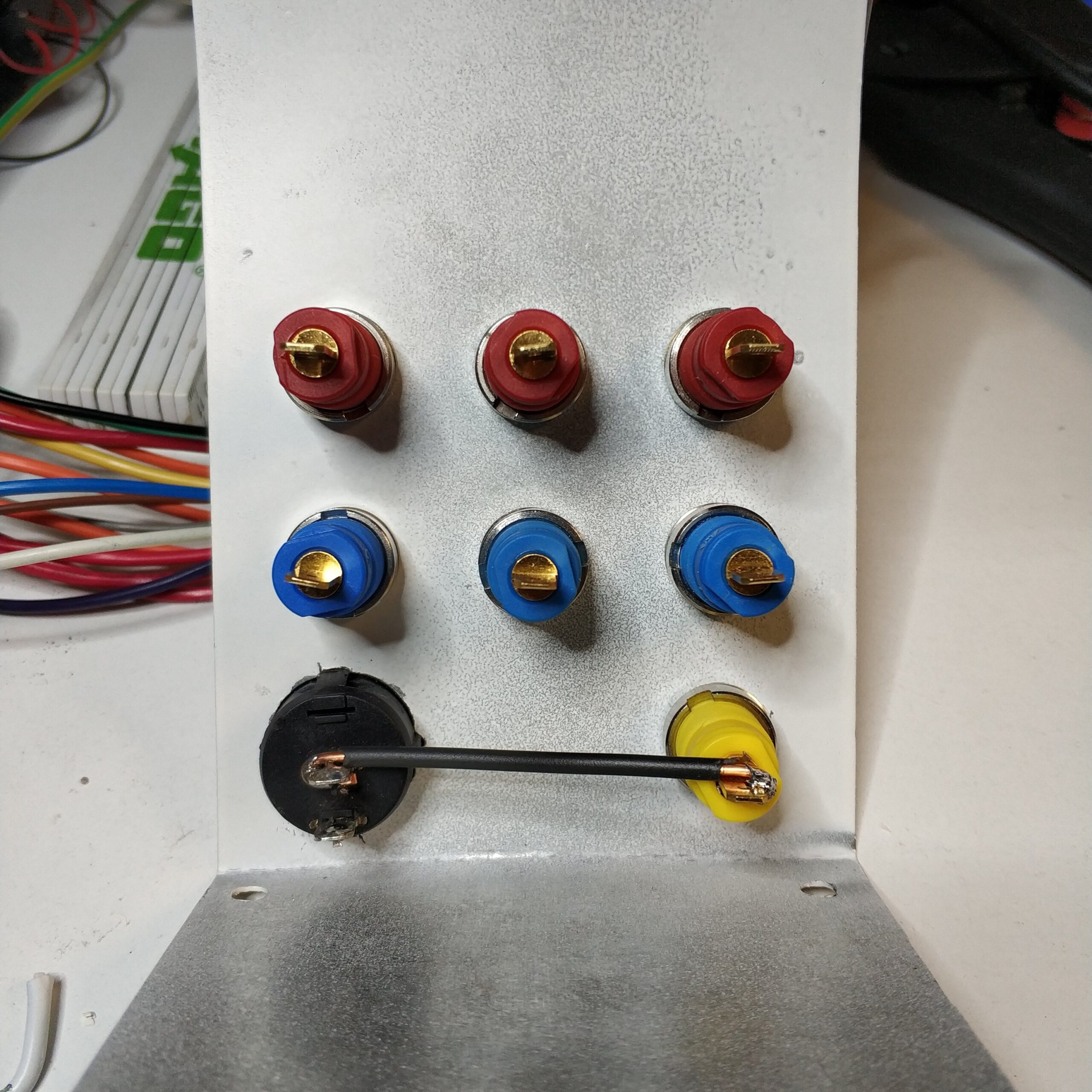
Nach dem biegen der runden Frontblende habe ich die Positionen der gezeigten Laborbuchsen eingezeichnet und gekörnt. Die roten Buchsen sind für die positiven Spannungen, die blauen für negative Spannungen und gelb/grün für 0V Spannung oder auch Masse.
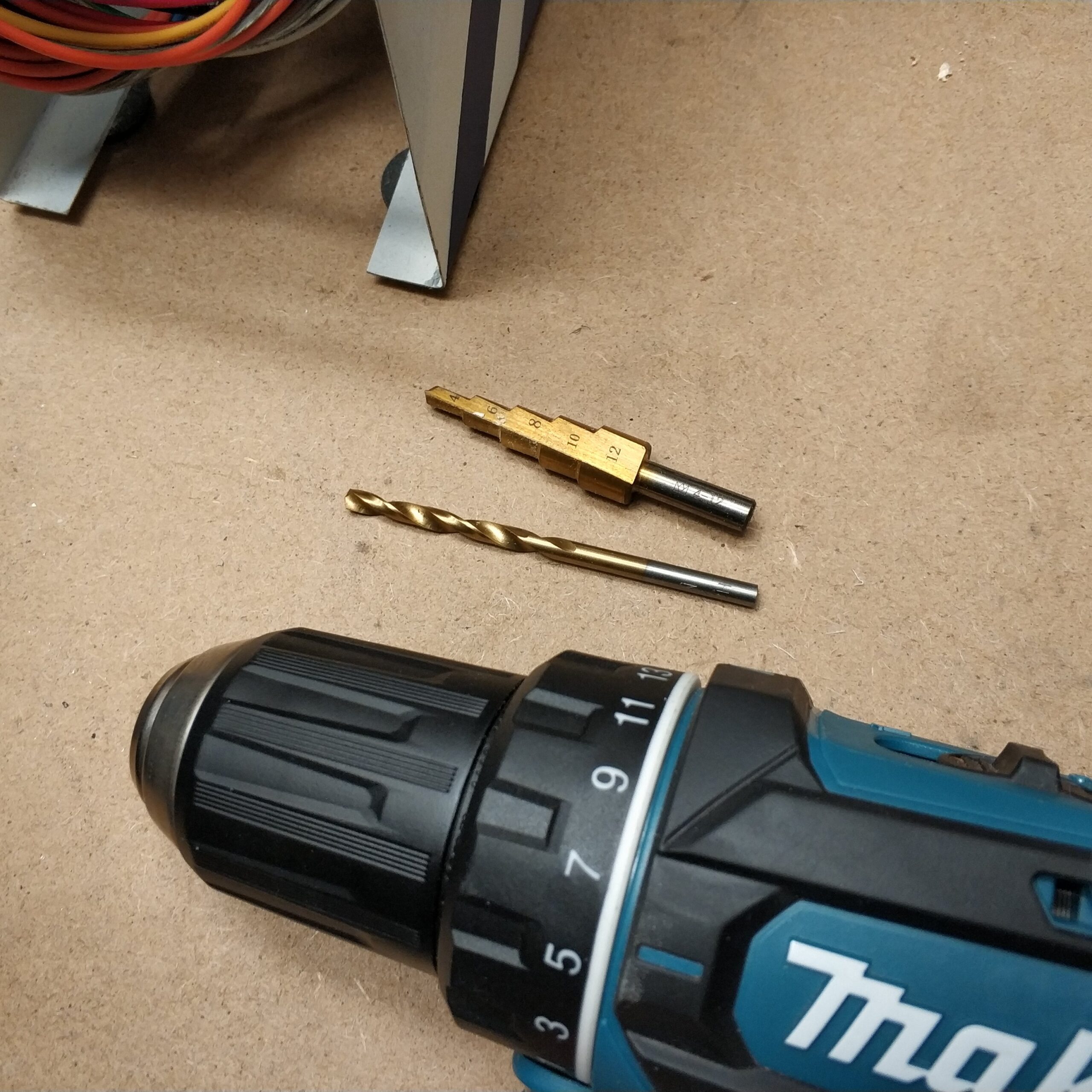
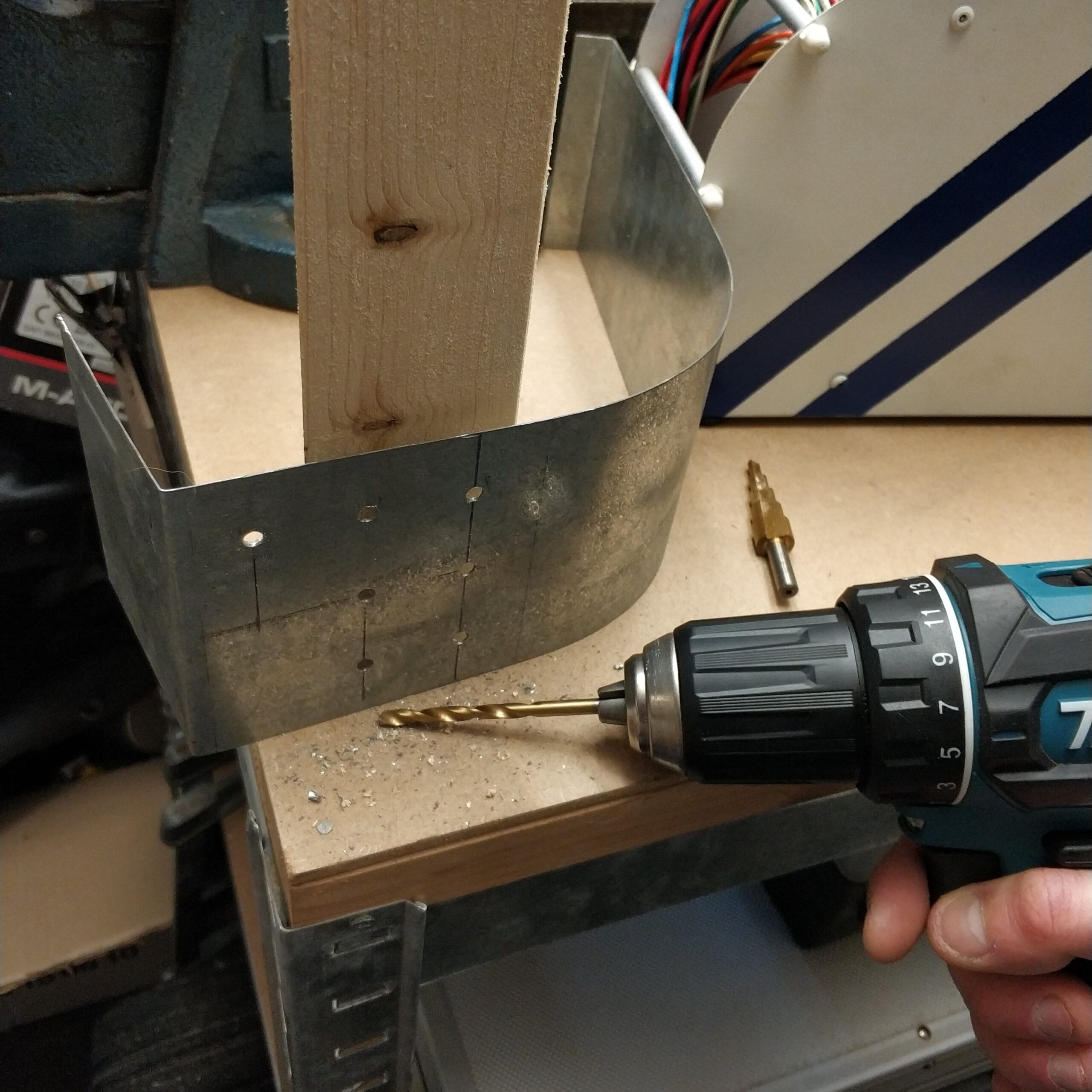
Nach dem vorbohren durch das Blech habe ich einen billigen Stufenbohrer die Löcher erweitert. Das hat mäßig funktioniert.
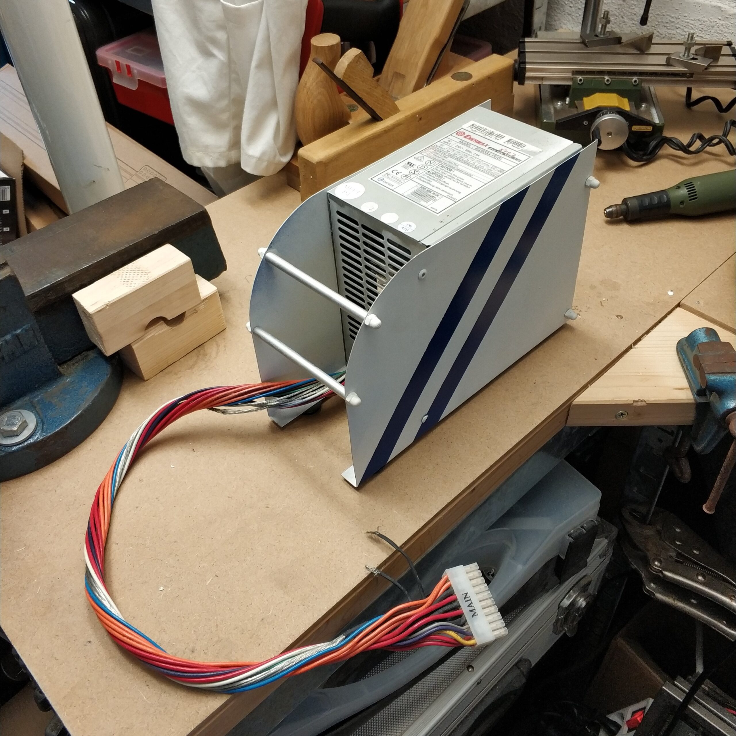
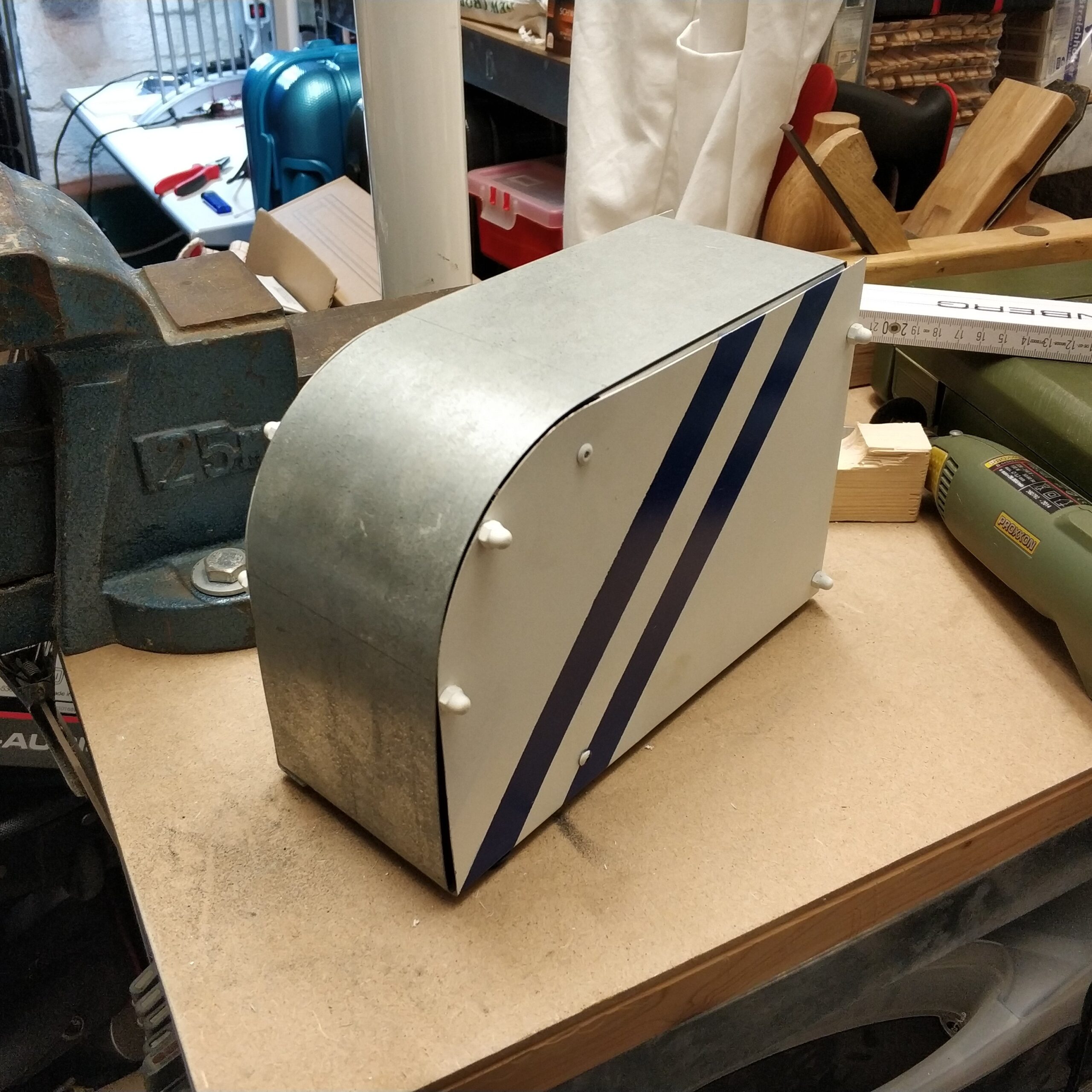
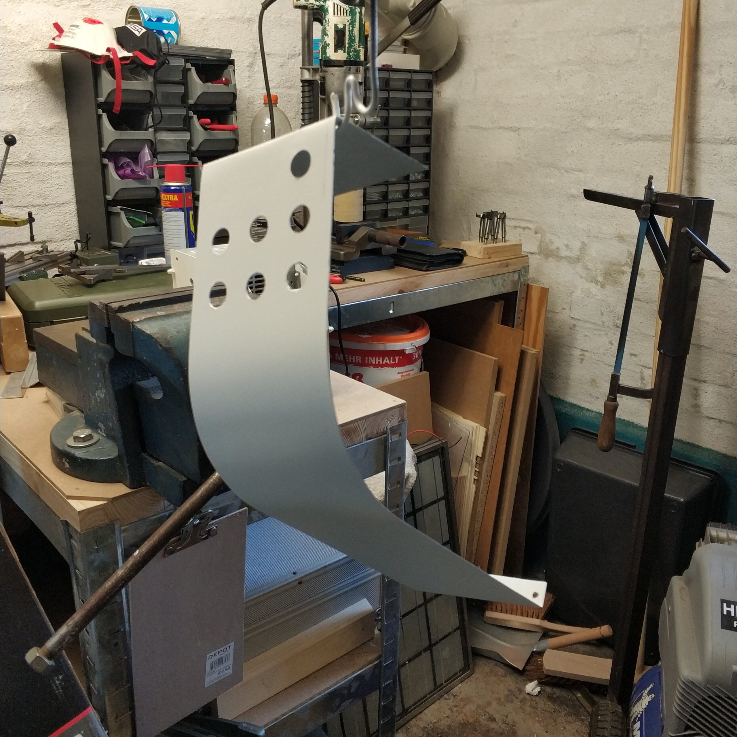
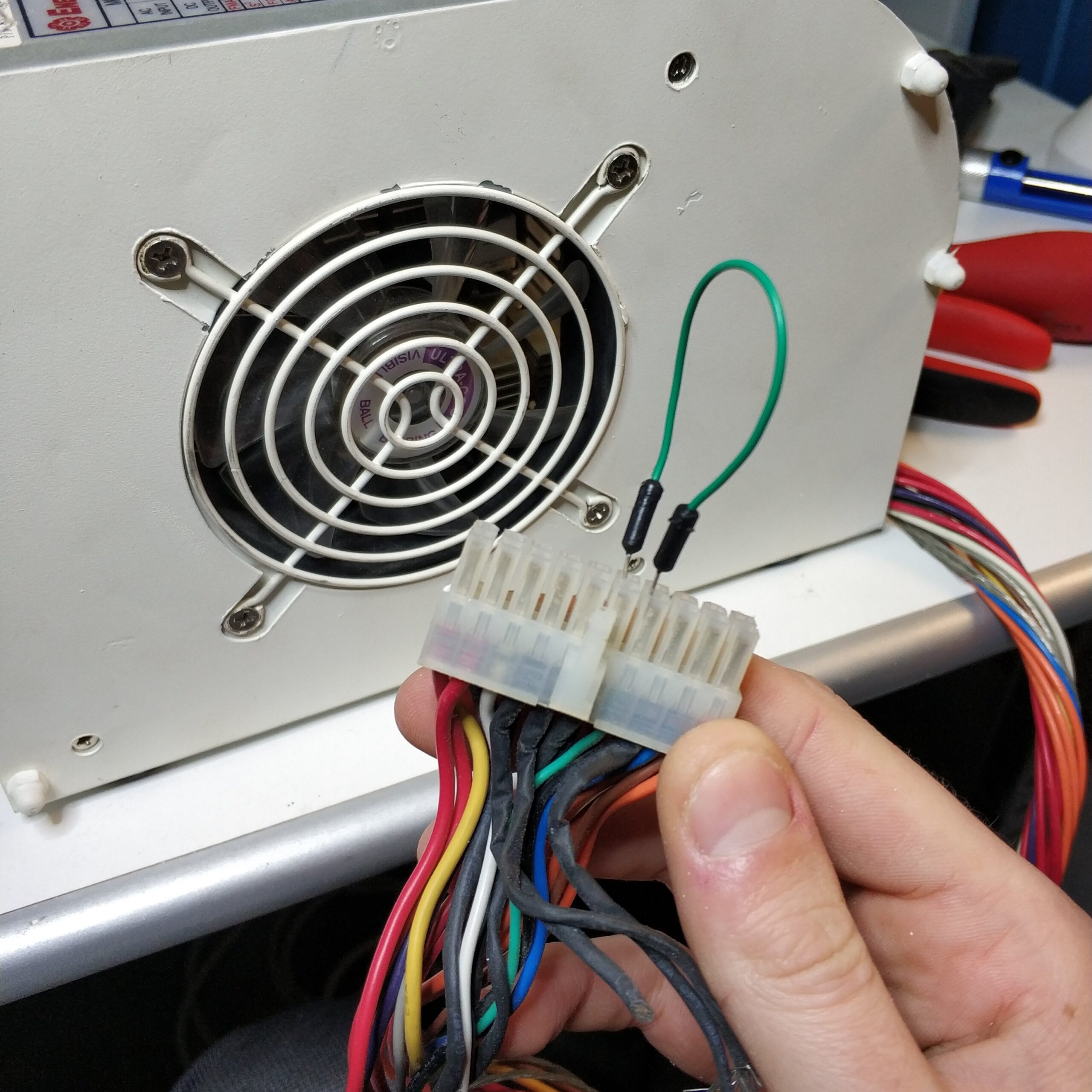
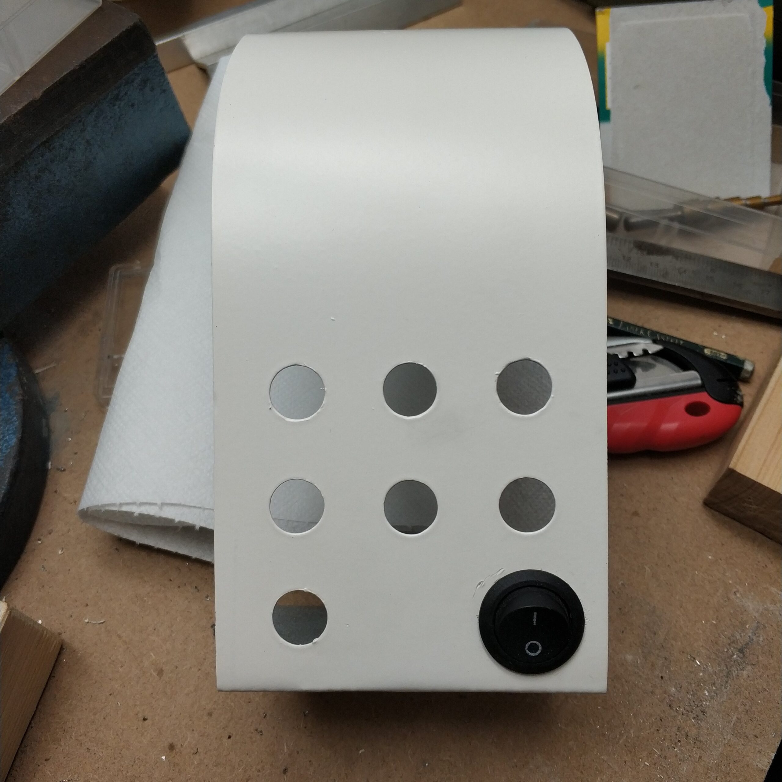
Anschließen hab ich das Blech lackiert und über Nacht trocknen lassen. Das war aber ein Fehler, da ich vergessen habe ein Loch für den Ein-/Ausschalter zu bohren. Denn wie in der Bildergalerie unten zu sehen ist muss man nämlich das grüne Kabel mit Masse kurzschließen, um das Netzteil zu starten. Das habe ich aber in den 5 Jahren vergessen und mich erst wieder damit beschäftigt als ich noch mal das Netzteil erfolglos starten wollte.
Bend sheet metal and drill holes
At that time I still managed to cut a galvanized sheet into the right width. The project was then put on hold because I didn’t see a good way to bend the front panel halfway adequately. One of these 3 in 1 sheet metal processing stations would be perfect, but then as now it is not worth buying. But with the vice and the sheet metal bending experience from the Bluetooth headphone project, I dared to do the whole thing.
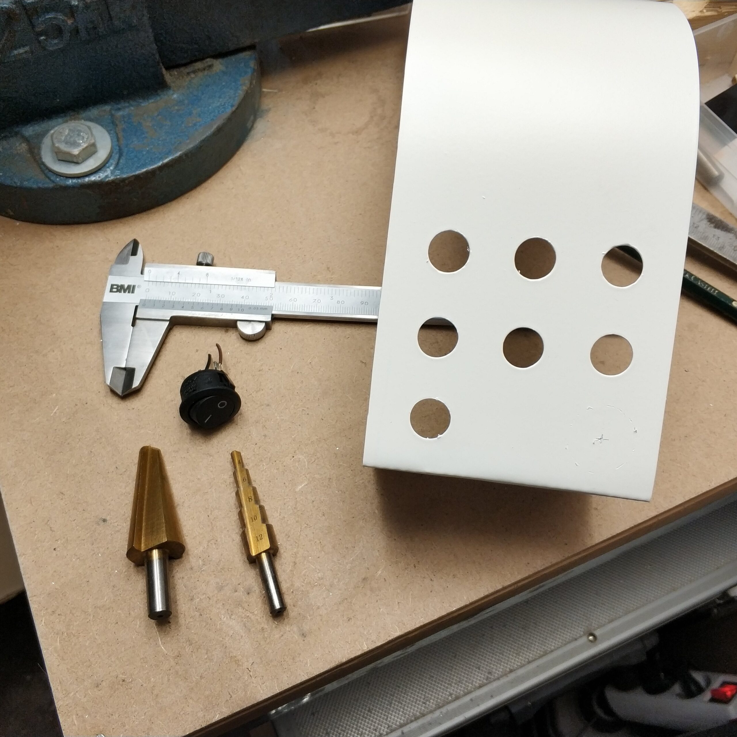
After bending the round front panel, I drew and marked the positions of the laboratory sockets shown. The red sockets are for positive voltages, the blue for negative voltages and yellow / green for 0V voltage or ground.
After pre-drilling through the sheet metal, I widened the holes with a cheap step drill. That worked moderately.
Then I painted the sheet metal and let it dry overnight. But that was a mistake because I forgot to drill a hole for the on / off switch. Because, as can be seen in the picture gallery below, you have to short-circuit the green cable to ground to start the power supply. But I forgot that in the 5 years and only dealt with it again when I tried to restart the power supply without success.
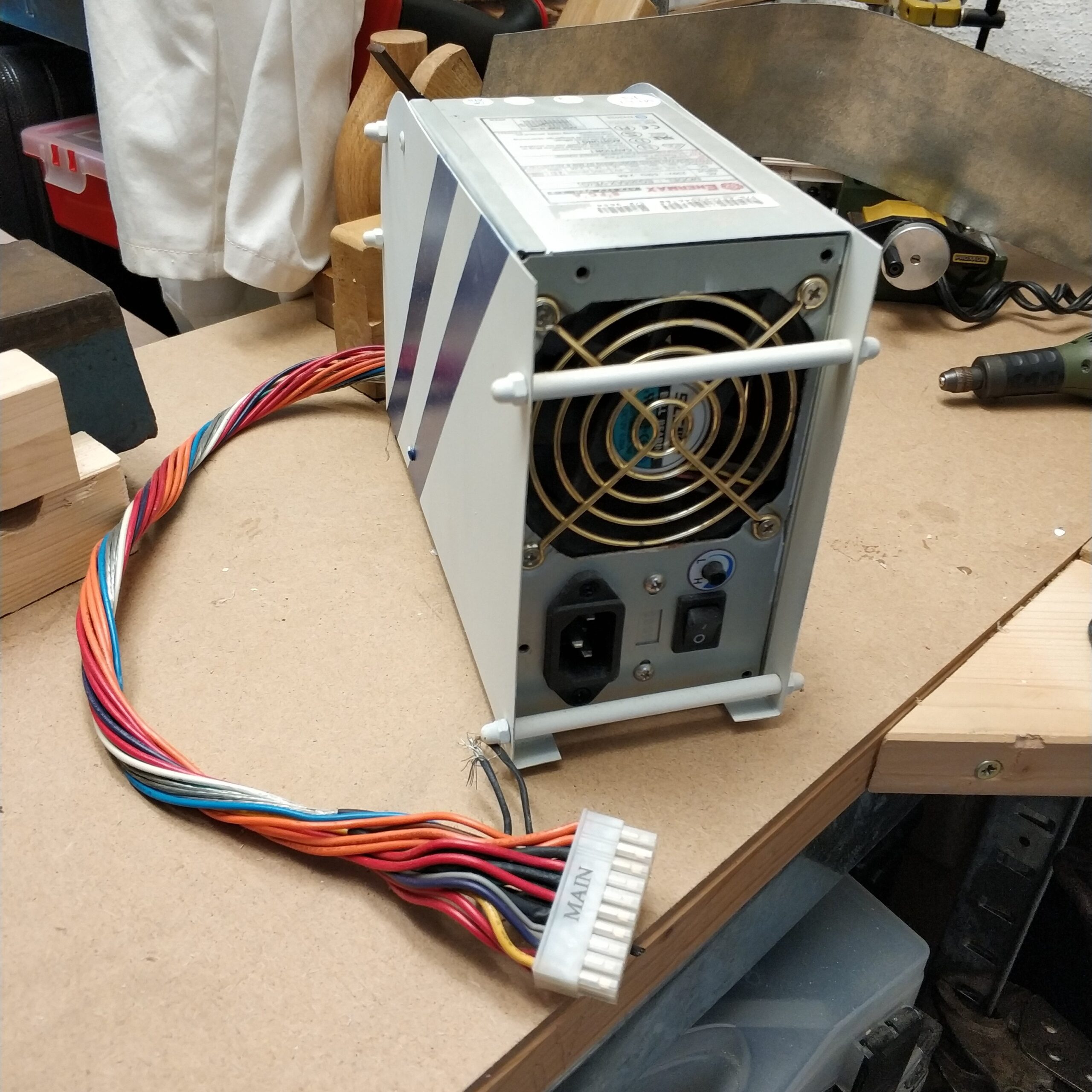
Verkabelung
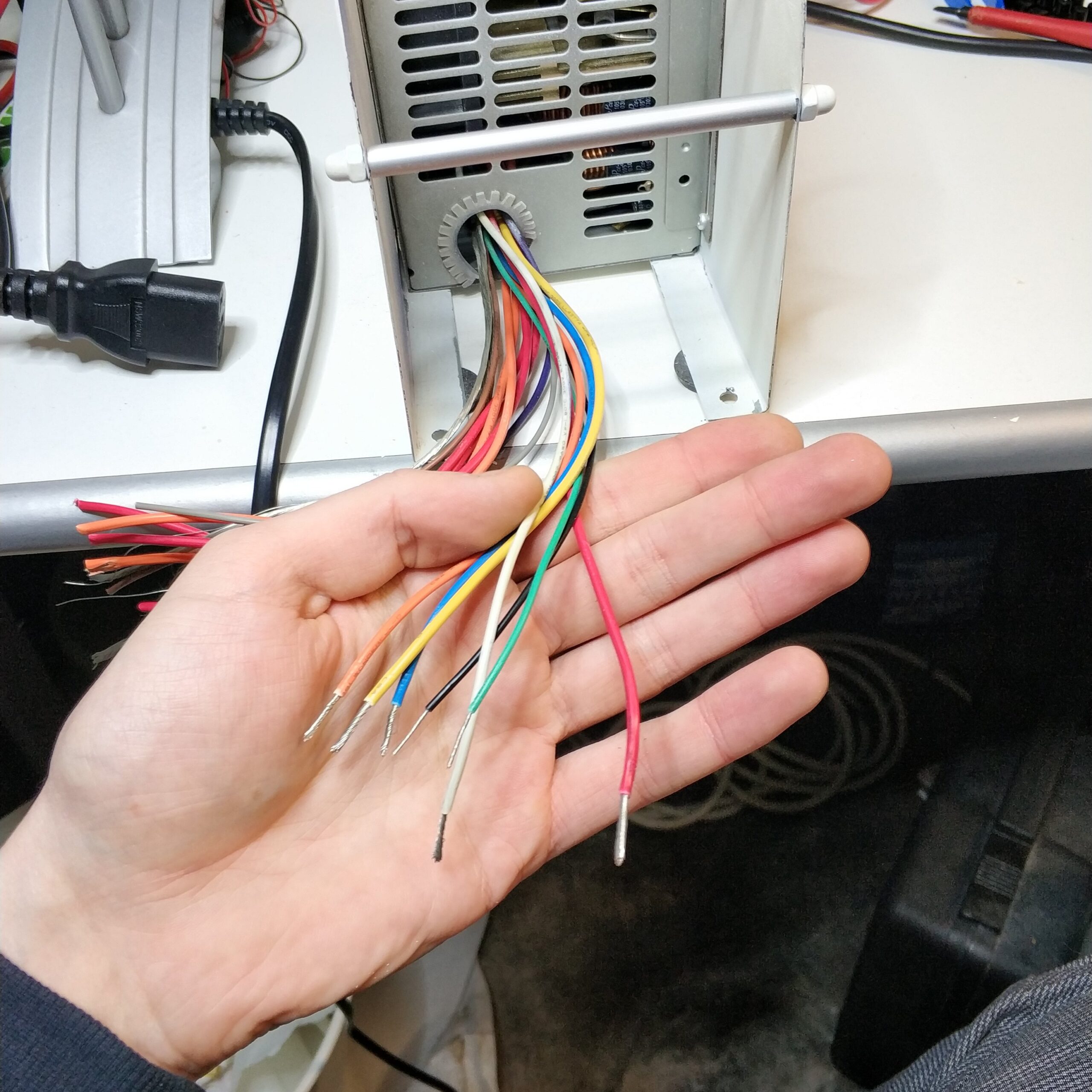
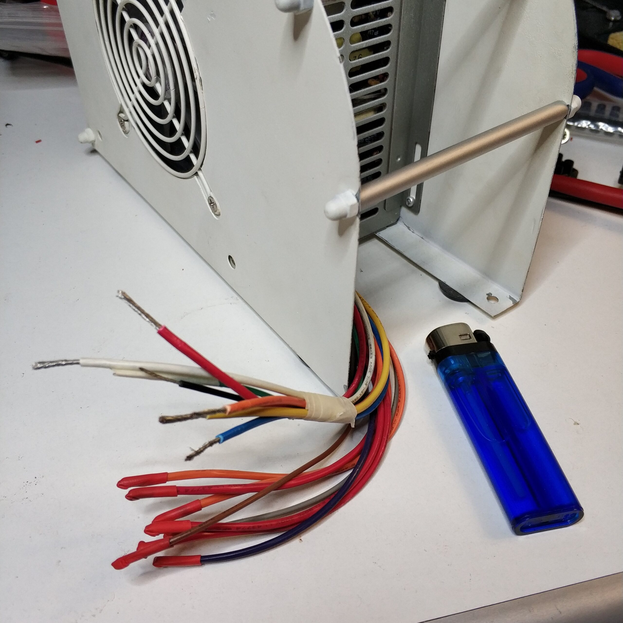
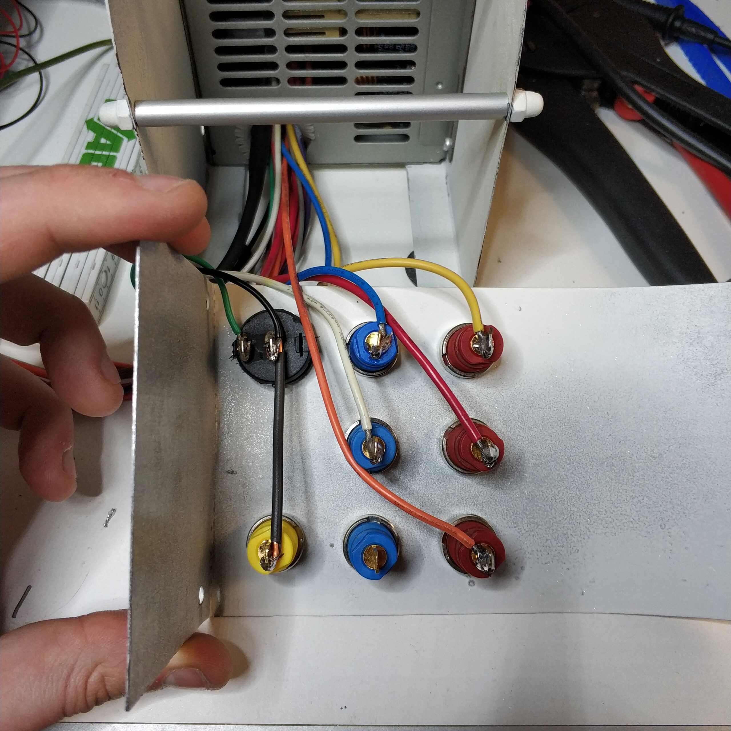
Dann war es aber an der Zeit sich mit den Kabeln des Netzteiles zu beschäftigen, damit das richtige Kabel an die Richtigen Buchse kommt. Aus der folgenden Grafik, die die Pinbelegung zeigt, kann man schnell entnehmen welche Kabel gebraucht werden:
schwarz (Masse/0V), orange (+3,3V), weiß (-5V), rot (+5V), blau (-12V), gelb (+12V) und grün für das Einschalten des Netzteils.
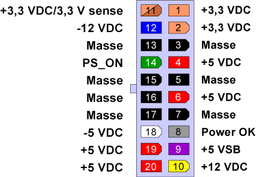
Achtung! Es gibt auch noch violett mit +5V was aber auch bei ausgeschaltetem Netzteil Strom liefert. Das nicht benutzen, sonst kann es unerwünschte Überraschungen geben wenn man denkt dass das Netzteil aus ist aber noch Spannung anliegt.
An dieser Stelle viel mir dann auch auf das ich eine Buchse zu viel habe. Die Buchse für die Spannung -3,3V hat das Netzteil nämlich gar nicht. Pech!
Hier habe ich dann auch das Loch für den Schalter gebohrt, was sehr schlecht ging, da das Loch 40mm groß sein musste aber mein anderer Stufenbohrer auch nur bis 40mm ging und deshalb immer durchrutschte. Die Lackierung hat auch durch die Aktion gelitten.
Für das Verkabeln habe ich dann erst einmal den Stecker abgeschnitten und alle Kabel auf eine passende Länge eingekürzt. Anschließend habe ich alle benötigten Kabel herausgesucht und doppelte und nicht benötigte Kabelenden isoliert.
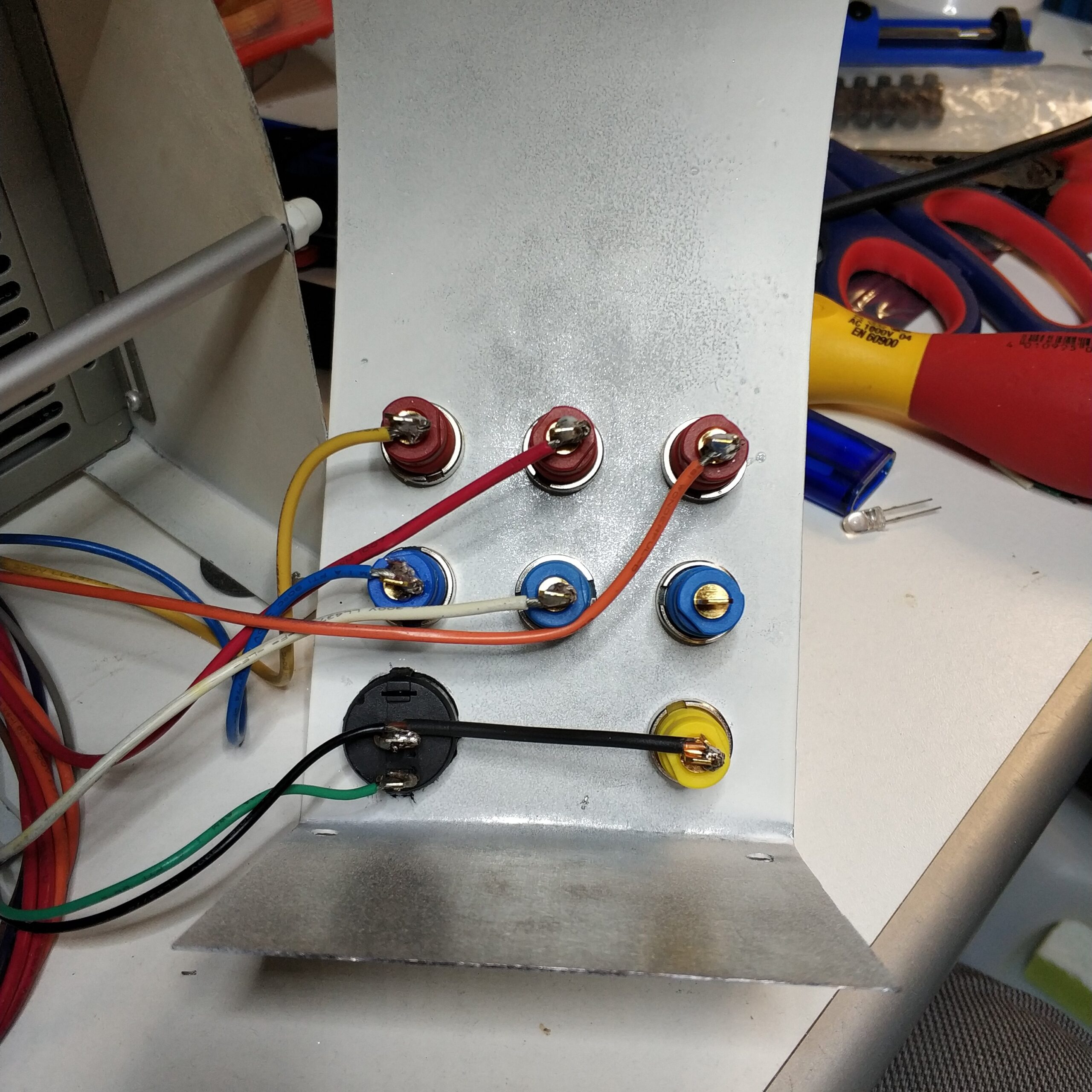
Nach dem Einbau des Schalters und der Buchsen habe ich ein dickes Kupferkabel aus Wandleitungen mit dem Schalter und der Masse Buchse verbunden. Alle anderen Kabel wurden dann mit den entsprechenden Buchsen und viel Lötzinn verbunden. Professioneller wären eigentlich gecrimpte Flachsteckhülsen gewesen, die ich aber nicht besitze, weil ich bisher nie welche gebraucht habe.
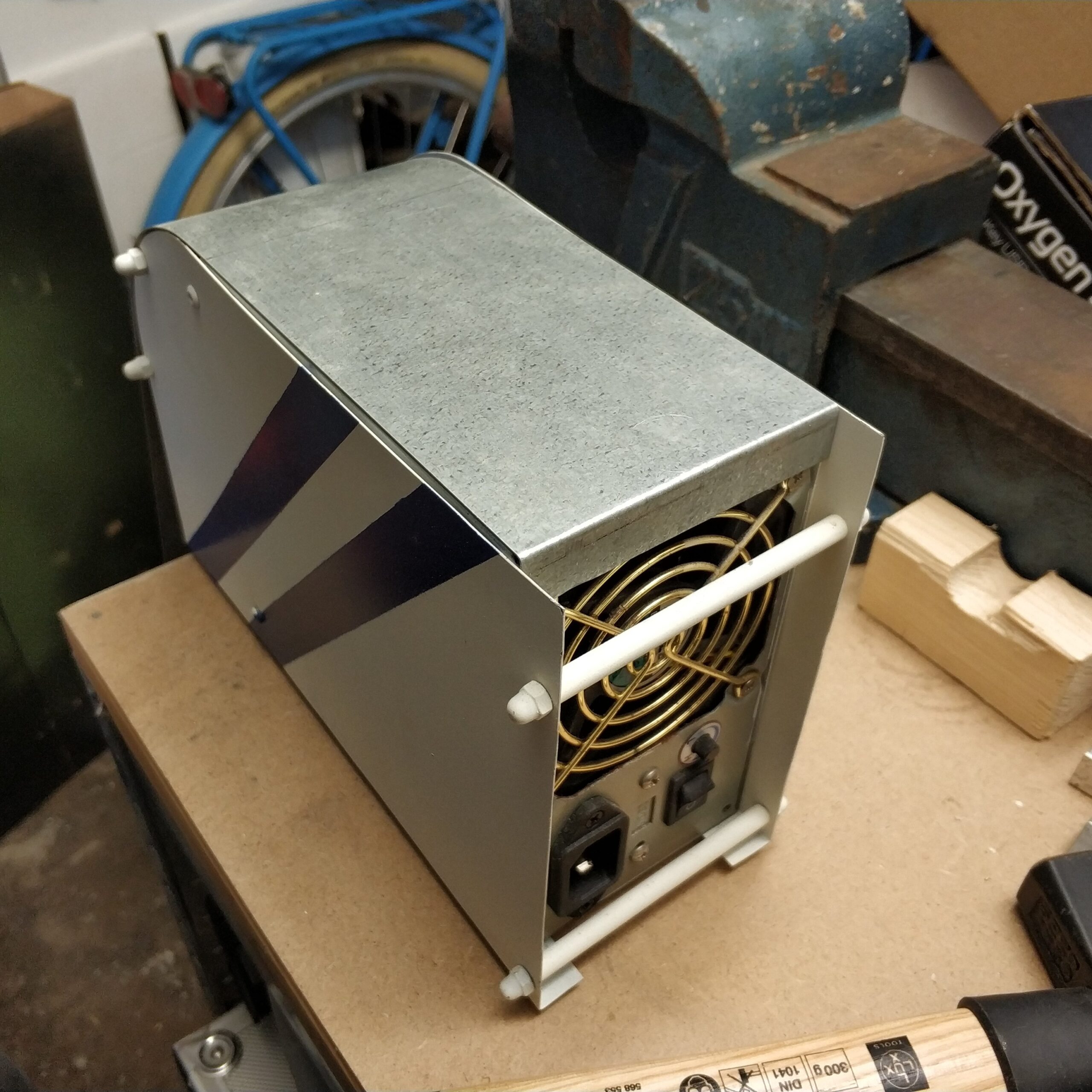
Zum Schluss habe ich die Frontblende auf das Netzteil gesetzt. Derzeit fehlen aber noch Löcher für M3 schrauben um die Frontblende hinten am Netzteil und unten mit den Seitenblechen zu verschrauben. Daher kann man noch Teilweise Kabel sehen und alles ist noch nicht ganz so stabil wie es sein könnte.
Wiring
Then it was time to deal with the cables of the power supply so that the right cable comes to the right socket. From the following graphic, which shows the pin assignment, you can quickly see which cables are needed:
black (ground / 0V), orange (+3.3V), white (-5V), red (+5V), blue (-12V), yellow (+12V) and green for switching on the power supply.
Attention! There is also purple with +5V, which also provides power when the power supply is switched off. Do not use that, otherwise there may be unwanted surprises if you think that the power supply is off but voltage is still present.
At this point I also think that I have one socket too many. The power supply does not have the socket for the voltage -3.3V. Bad luck!
Here I also drilled the hole for the switch, which went very badly, because the hole had to be 40mm but my other step drill only went up to 40mm and therefore always slipped through. The paintwork also suffered from the action.
For the wiring, I first cut off the connector and shortened all the cables to a suitable length. Then I picked out all the cables I needed and insulated double and unneeded cable ends.
After installing the switch and sockets, I connected a thick copper cable made of wall leads to the switch and the ground socket. All other cables were then connected to the appropriate sockets and lots of solder. Crimped flat receptacles would have been more professional, but I don’t own them because I’ve never used them before.
Finally, I put the front panel on the power supply. At the moment there are still missing holes for M3 screws to screw the front panel at the back of the power supply and at the bottom with the side plates. Therefore you can still see some cables and everything is not as stable as it could be.
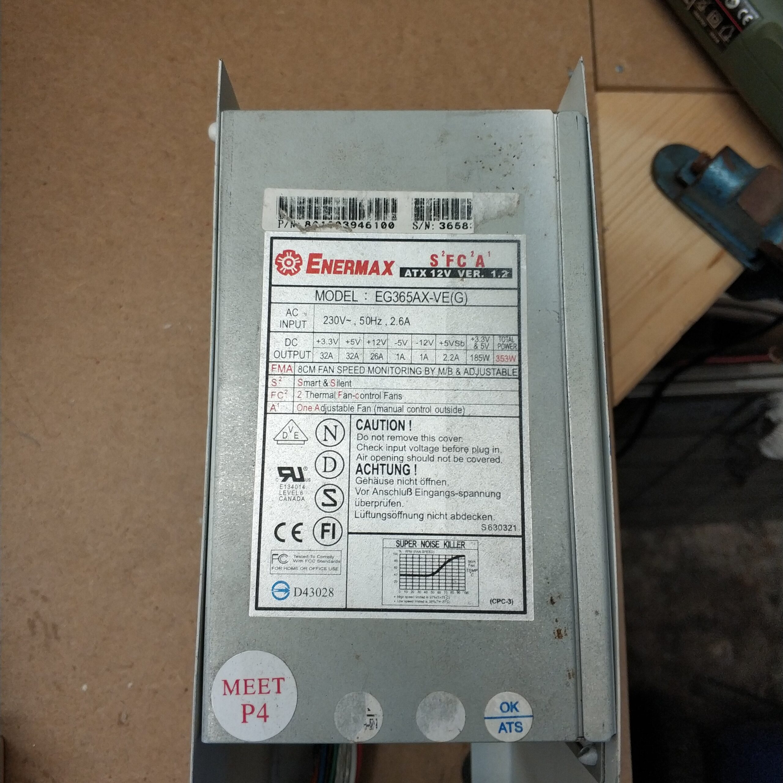
PC Netzteil Spannungen
Beim PC Netzteil kann man nur bestimmte Spannungen erhalten, in dem man die vorhandenen Spannungen miteinander kombiniert. Somit ist die Spannung ohne weiteres nicht frei regelbar was bei manchen Anwendungen ein Problem sein kann.
Das PC Netzteil erzeugt 6 Spannungen, die miteinander kombiniert werden:
0V, +3,3V, -5V, +5V, -12V und +12V
Daraus resultieren folgende möglich Spannungen:
1,7V → +3,3V mit +5V
3,3V → 0V mit +3,3V
5V → 0V mit +5V
7V → -12V mit -5V oder +5V mit +12V
8,3V → -5V mit +3,3V
8,7V → +3,3V mit +12V
10V → -5V mit +5V
12V → 0V mit +12V
15,3V → -12V mit +3,3V
17V → -12V mit +5V oder -5V mit +12V
24V → -12V mit +12V
Auch ohne ein regelbares Labornetzteil lassen sich so trotzdem eine Vielzahl an Spannungen erzeugen. Persönlich wären noch -15V und +15V schön, um noch 3V, (11,7V), 18,3V, 20V, 27V und 30V zu erhalten.
PC power supply voltages
With the PC power supply you can only get certain voltages by combining the existing voltages. Thus the voltage cannot be freely regulated without further ado, which can be a problem in some applications.
The PC power supply unit generates 6 voltages that are combined with one another:
0V, +3.3V, -5V, +5V, -12V and +12V
This results in the following possible stresses:
1.7V → +3.3V with +5V
3.3V → 0V with +3.3V
5V → 0V with +5V
7V → -12V with -5V or +5V with +12V
8.3V → -5V with +3.3V
8.7V → +3.3V with +12V
10V → -5V with +5V
12V → 0V with +12V
15.3V → -12V with +3.3V
17V → -12V with +5V or -5V with +12V
24V → -12V with +12V
Even without an adjustable laboratory power supply, a large number of voltages can still be generated. Personally, -15V and +15V would be nice to still get 3V, (11.7V), 18.3V, 20V, 27V and 30V.