

Design
Prepare
Build
Test
Done!

Man muss es leider so sagen, Skullcandy verkauft unausgereiften Müll, der nach wenigen Monaten kaputt geht. Ich habe von Skullcandy auch die erste Version der Crusher’s besessen, bei denen sich das Material an den Höhrmuscheln komplett abgelöst hat sowie der Kunststoff oben am Kopfpolster. Die Bassfunktion hat auch von einem auf den anderen Tag den geist aufgegeben.
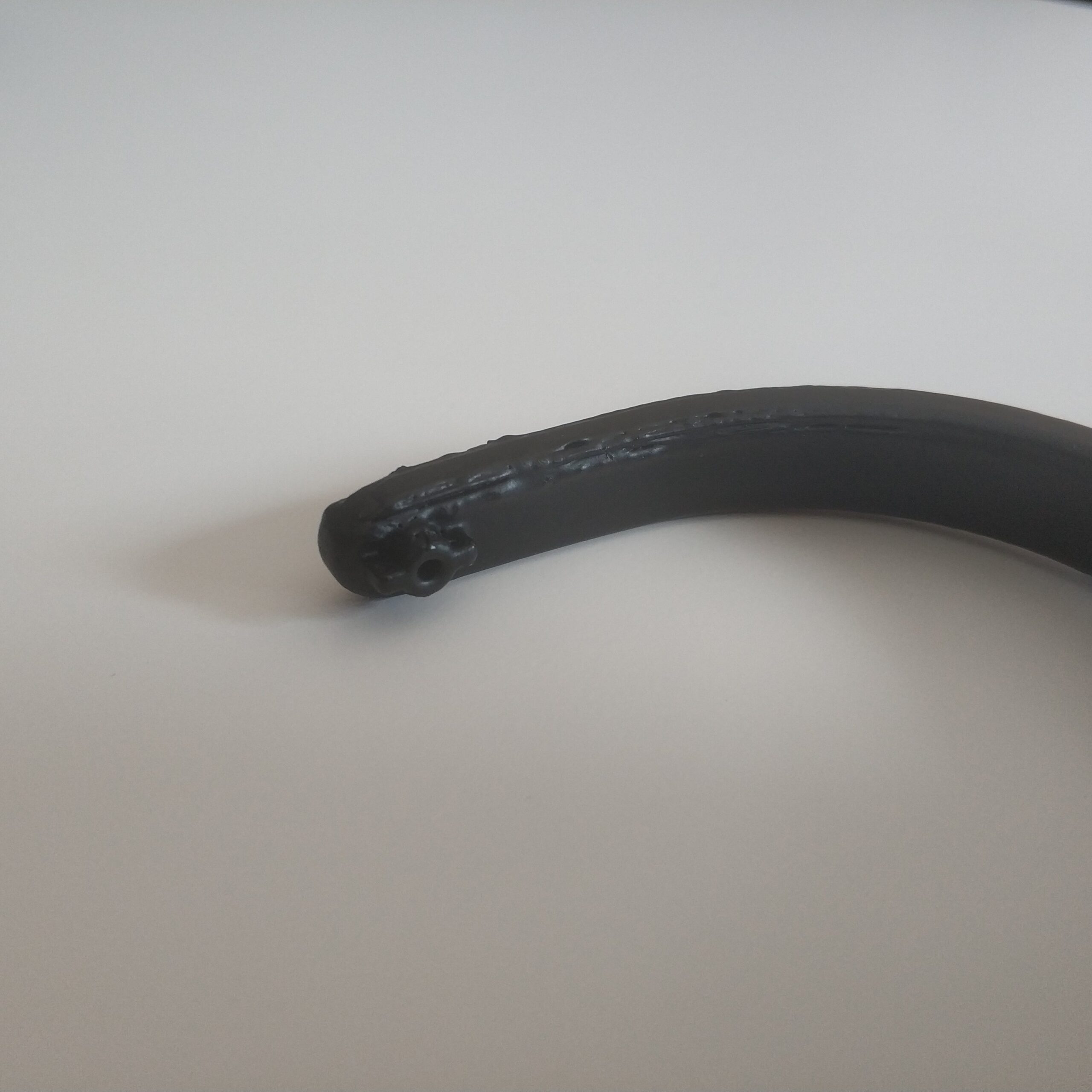
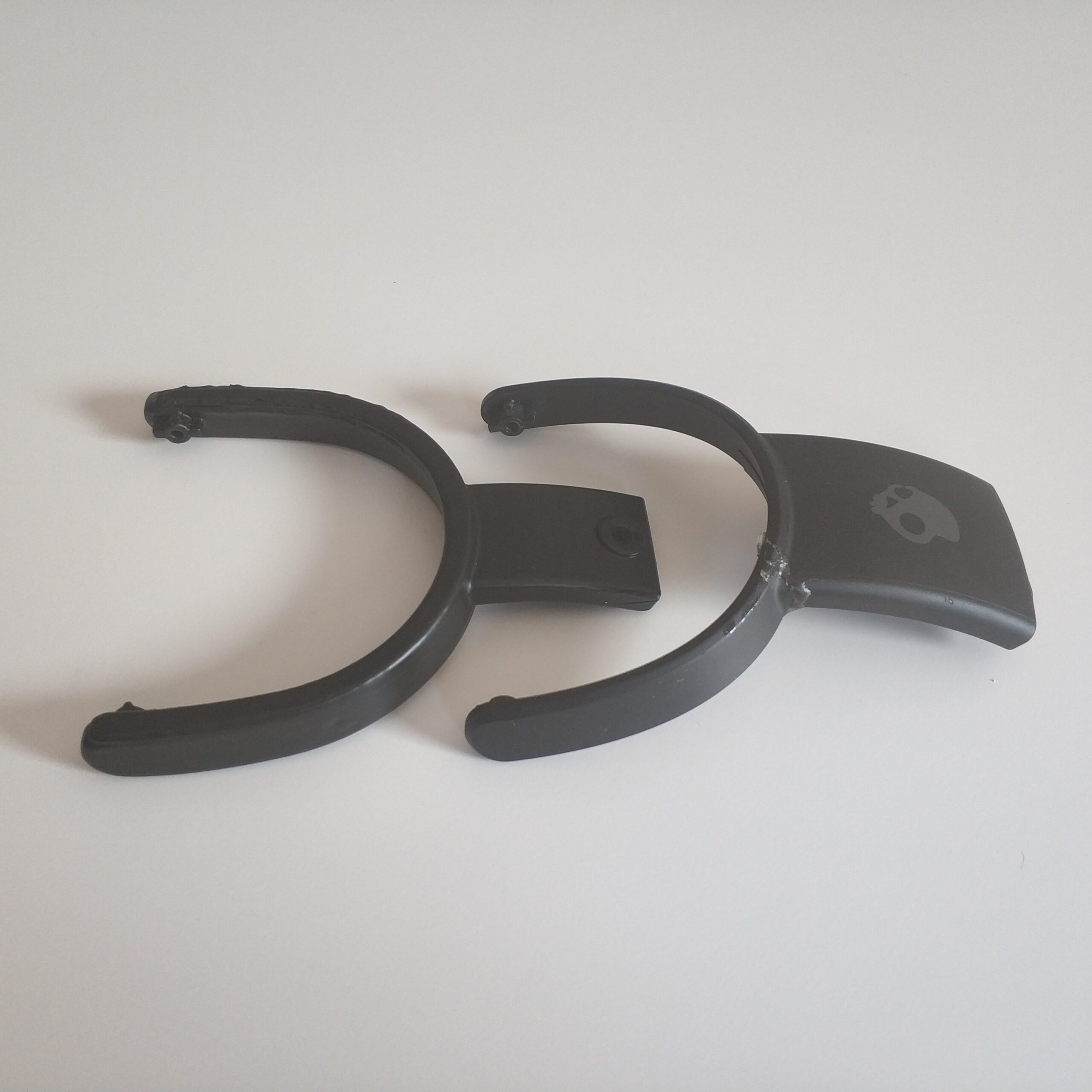
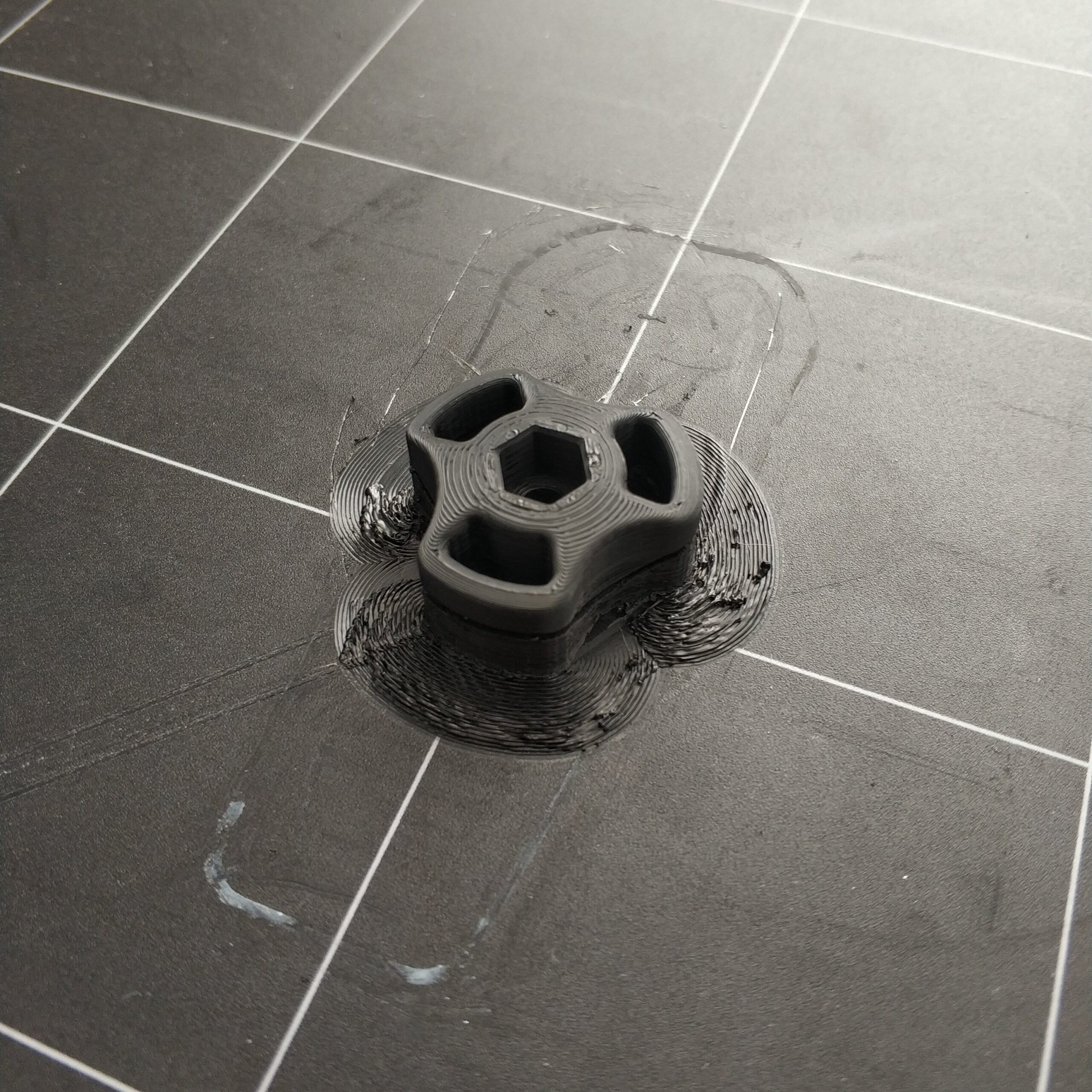
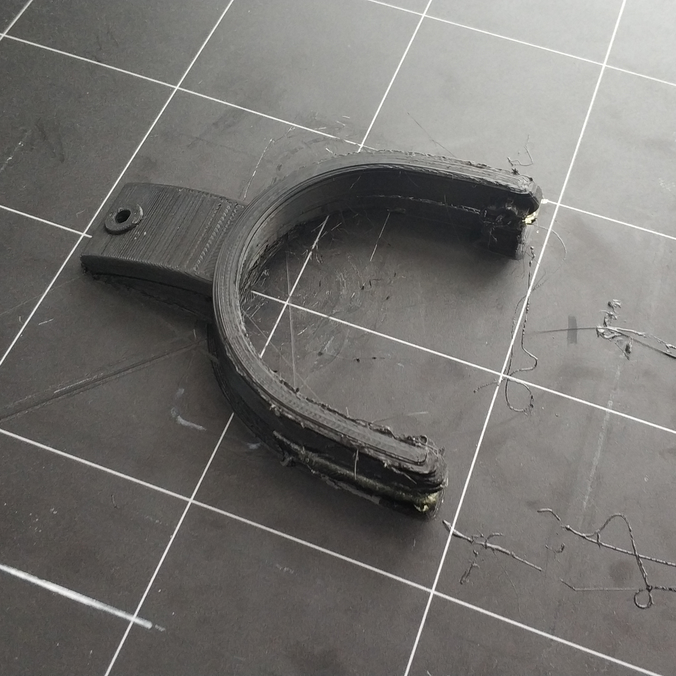
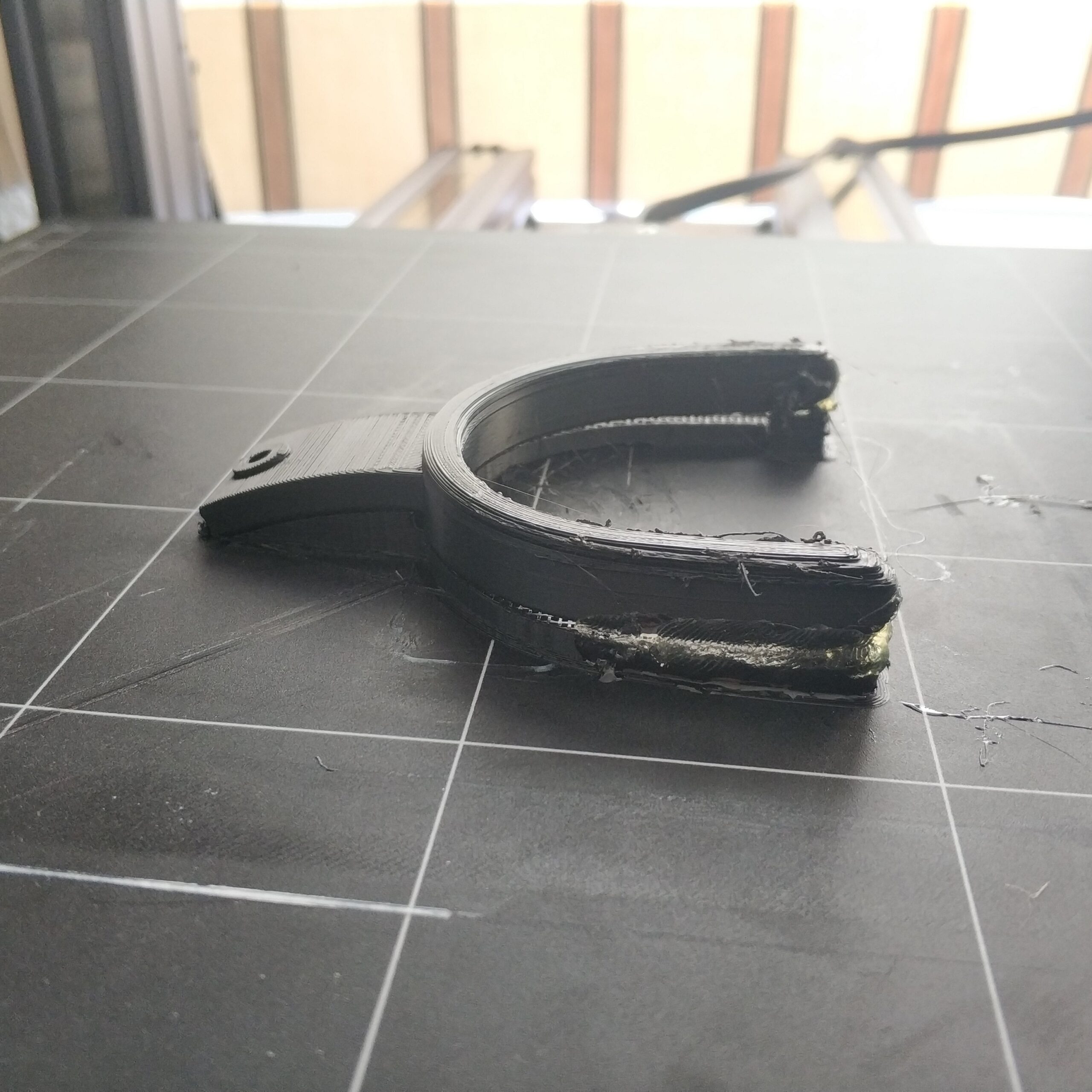
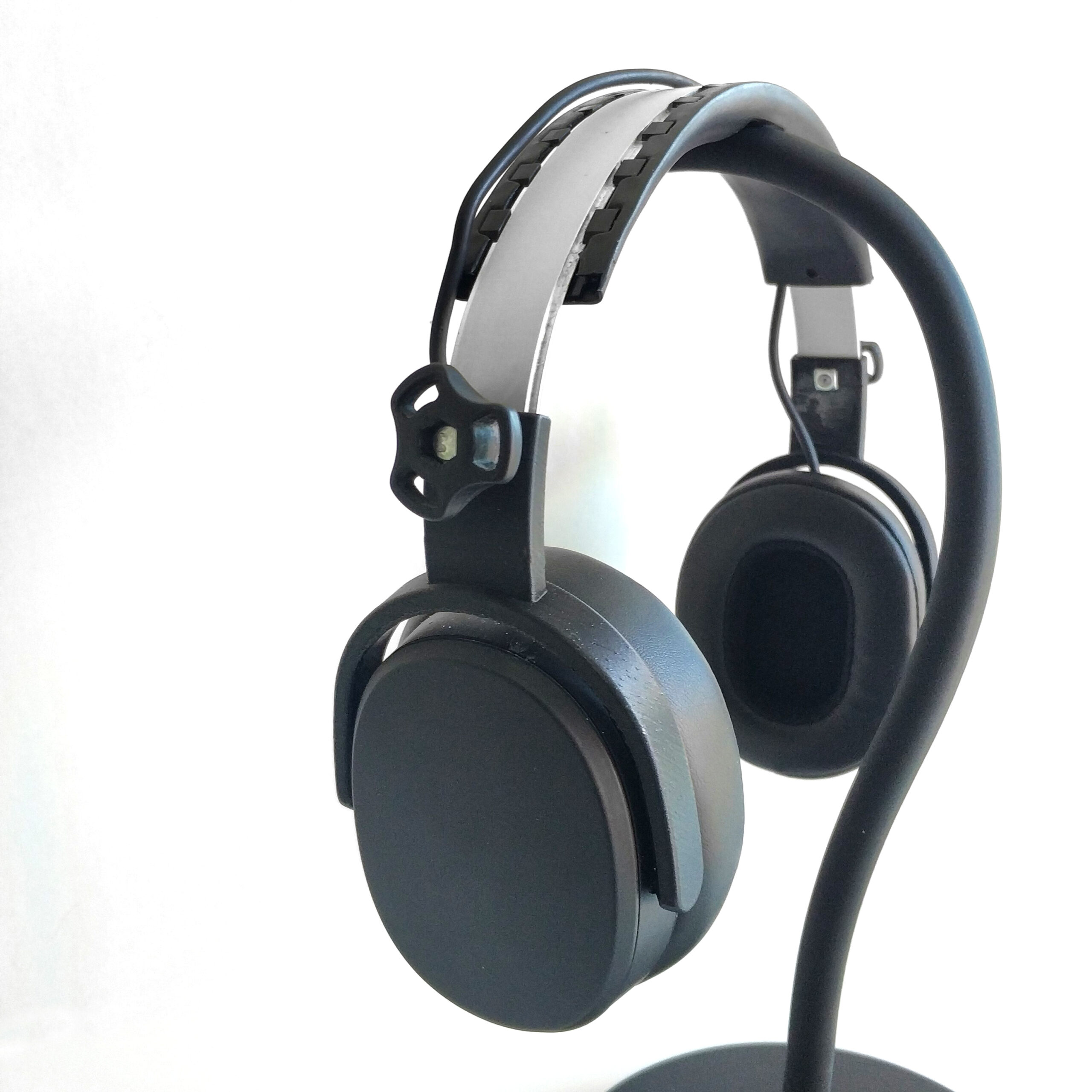
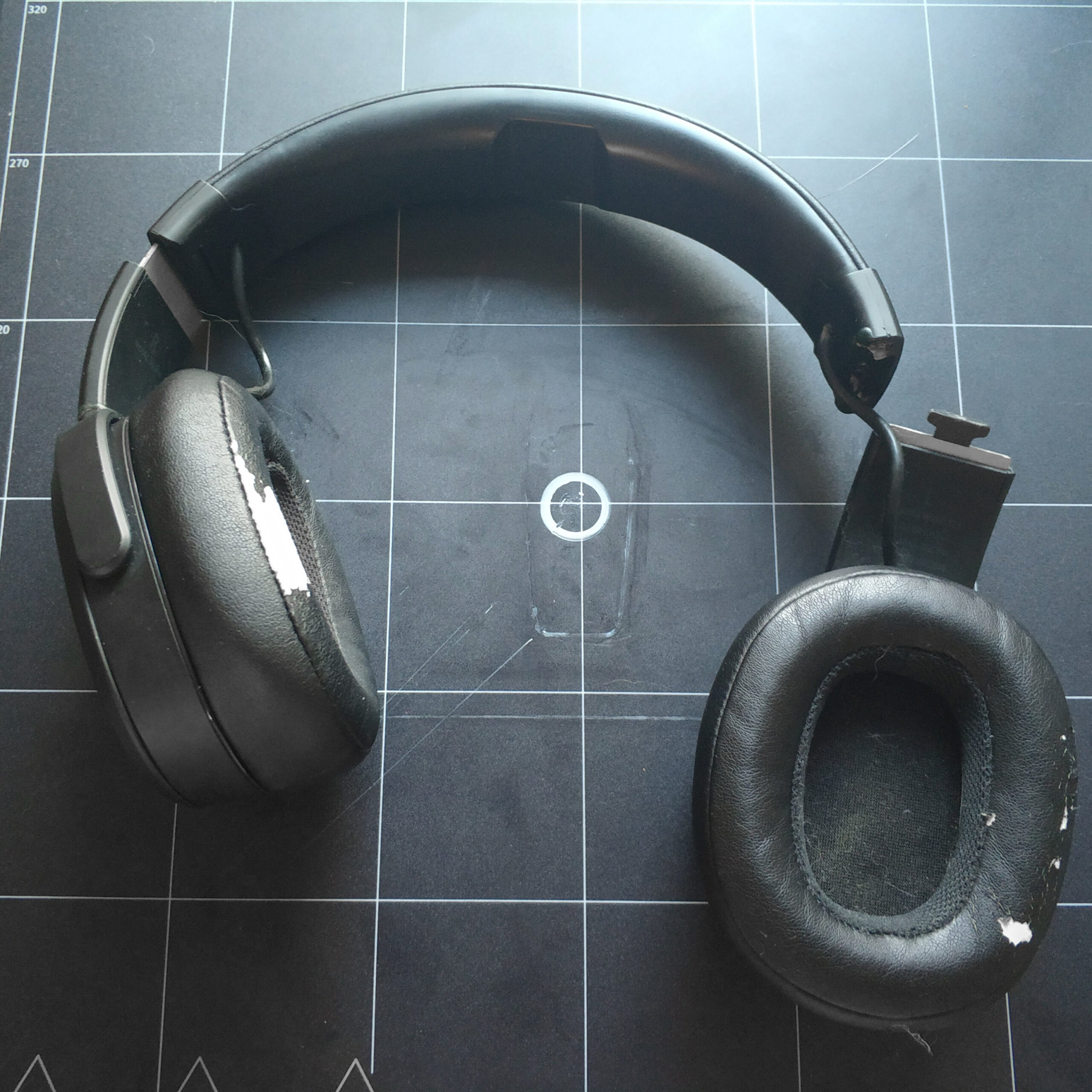
In der Hoffnung das die Wireless Version besser und ausgereifter sei habe ich mir diese als Ersatz für die alten gekauft. Aber auch hier hat sich nach einigen Monaten das Material von den Höhrmuscheln abgelöst (s. Bild) und schlimmer noch das Gelenk zum zusammenklappen ist auch nach wenigen Monaten auf beiden Seiten ganz oder Teilweise gebrochen, was die Kopfhöher trotz immerhin voller funktionsfähiger Elektrik unbrauchbar gemacht hat. Auch gebrochen sind die Übergänge zu den „U“ förmigen Trägern auf beiden Seiten, da diese aus Gründen des Zusammenbaus (aber hauptsächlich ästhetisch Gründen) nicht massiv sind sondern aus zwei Teilen bestehen. Zuerst hatte ich noch versucht mit 2K Kleber all die Gebrochenen Teile zusammen zu kleben oder zu stabilisieren aber mit mäßigem Erfolg.
Was man dem Kopfhörer lassen muss ist das er edel aussieht. Das nützt einem nur nicht viel wenn durch schlechte Konstruktion schnell kaputt geht. Es ist immer noch ein Gebrauchsgegenstand.
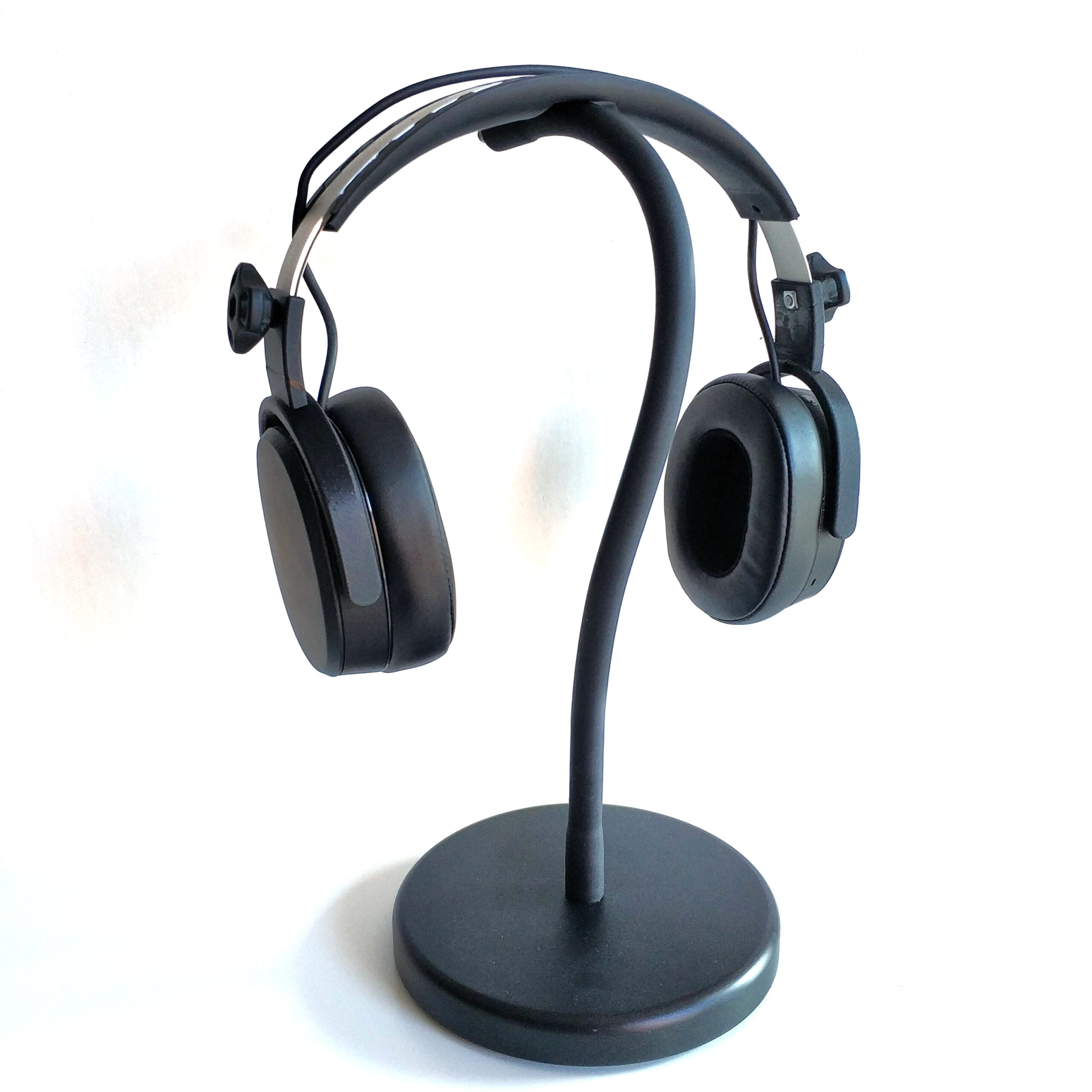
Da die Kopfhöher mich 130€ gekostet haben und diese technisch funktionieren wolle ich diesen ein neues Leben einhauchen.
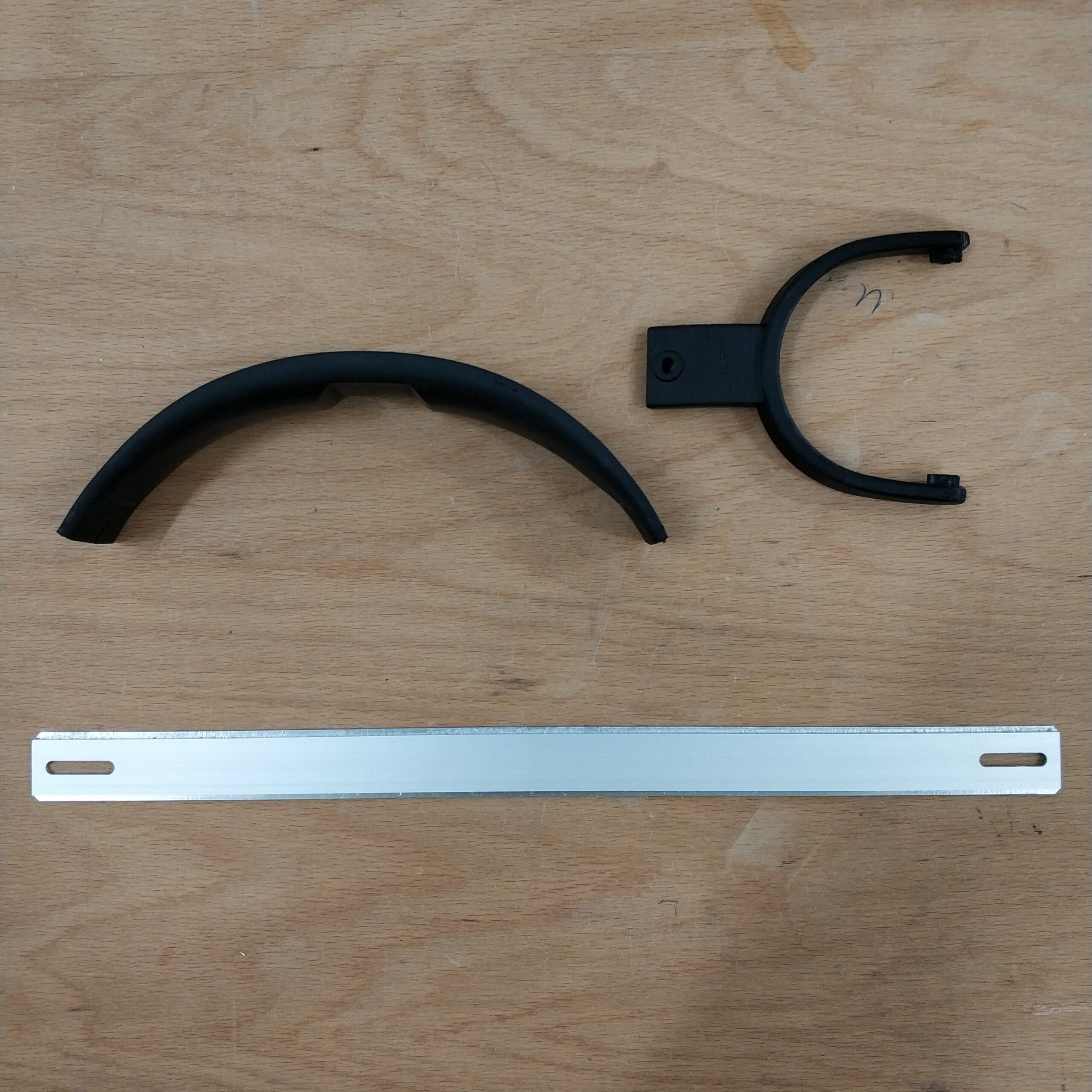
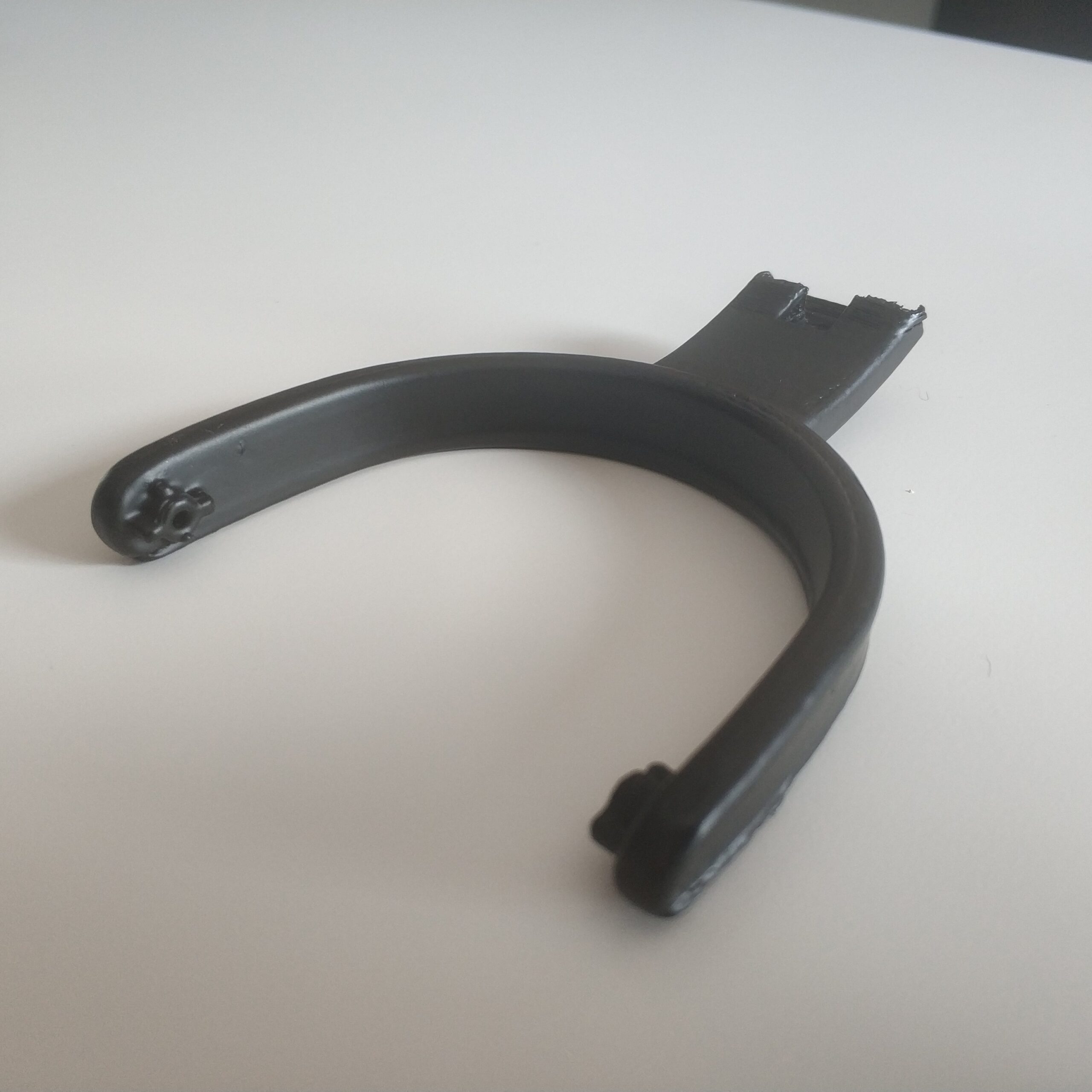
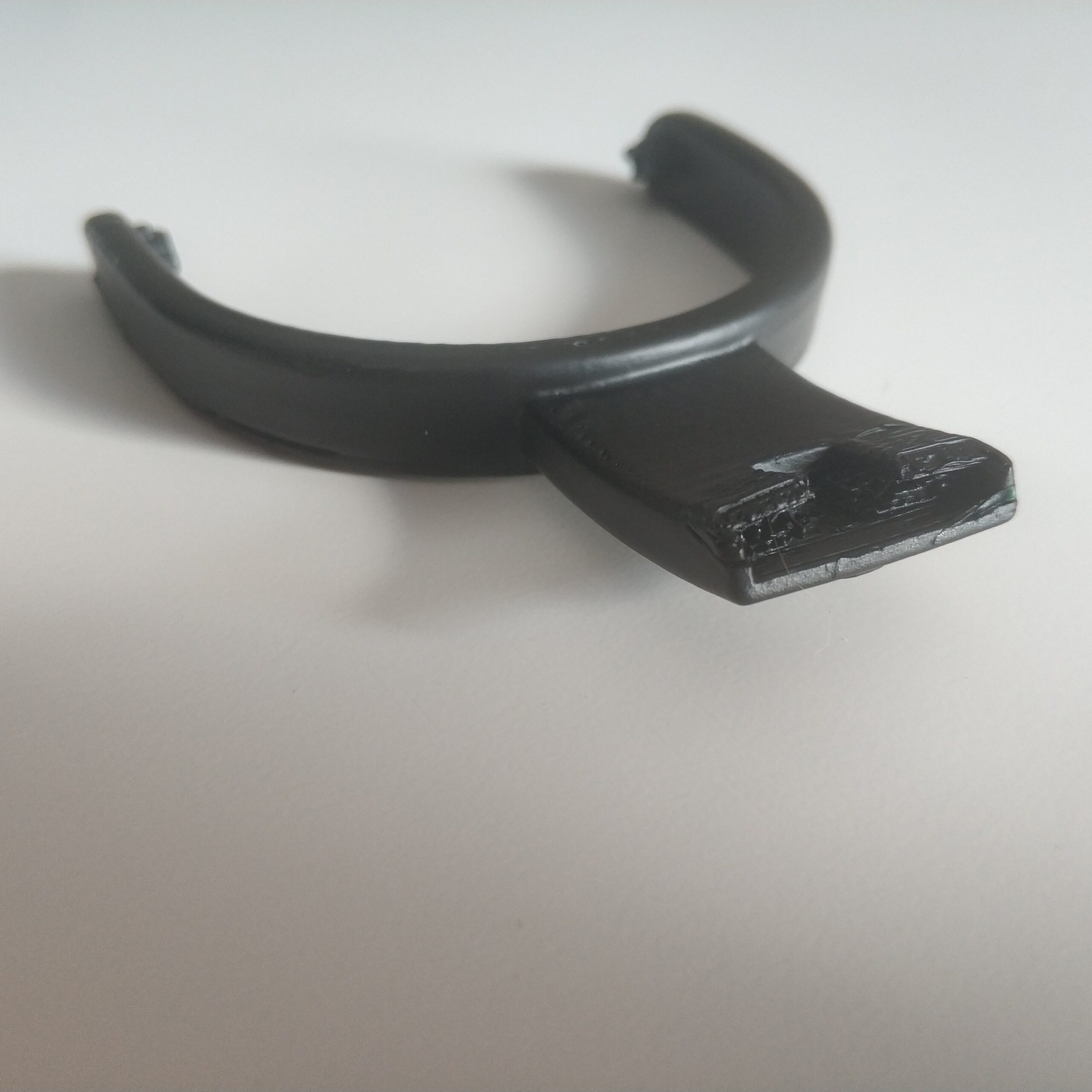
Der Plan war die Kaputen Kopfhörer soweit es geht auseinander zu bauen und funktionierende Komponenten zu erhalten, was am Ende nicht so viel war. Neben den beiden Kunststoffteilen mit der Technik darin, hat es nur noch das Kopfpolster in das neue Design geschafft.
An dieser stelle möchte ich den vermutlich Asiatischen Arbeitern mein Beileid aussprechen die diese zusammenbauen müssen. Es gibt ziemlich viele Schrauben um die vielen Einzelteile zusammen zu halten und das Kabel, das beide Seiten verbindet, muss wohl vorher durch diverse Löcher gefädelt werden, was nahe legt das am ende die Kabel im weitestgehend zusammengebauten Zustand angelötet werden oder man während des Zusammenbauens nur durch das Kabel zusammen gehaltene lose Teile auf dem Tisch hat.
Unfortunately, you have to put it this way, Skullcandy sells unripe garbage that breaks after a few months. I also owned the first version of the Crusher’s from Skullcandy, in which the material on the ear cups has completely peeled off as well as the plastic on the top of the head pad. The bass function also gave up the ghost from one day to the next.
In the hope that the wireless version would be better and more sophisticated, I bought this as a replacement for the old one. But here, too, after a few months, the material has detached from the ear cups (see picture) and, even worse, the joint for folding up is completely or partially broken on both sides after a few months, which has made the headphones unusable despite at least fully functional electrics . The transitions to the „U“ -shaped girders on both sides are also broken, since for reasons of assembly (but mainly for aesthetic reasons) they are not massive but consist of two parts. At first I tried to glue all the broken parts together with 2K glue or to stabilize them but with moderate success.
What you have to give the headphones is that they look classy. It’s just not of much use if it breaks quickly due to poor construction. It’s still a commodity.
Since the headphones cost me 130 € and they work technically, I want to breathe a new life into them.
The plan was to disassemble the broken headphones as much as possible and get working components, which in the end wasn’t that much. In addition to the two plastic parts with the technology in them, only the head cushion has made it into the new design.
At this point I would like to express my condolences to the probably Asian workers who have to assemble them. There are quite a few screws to hold the many individual parts together and the cable that connects both sides must be threaded through various holes beforehand, which suggests that at the end the cables are soldered on in the largely assembled state or you only need to do it during assembly Has loose parts held together by the cable on the table.
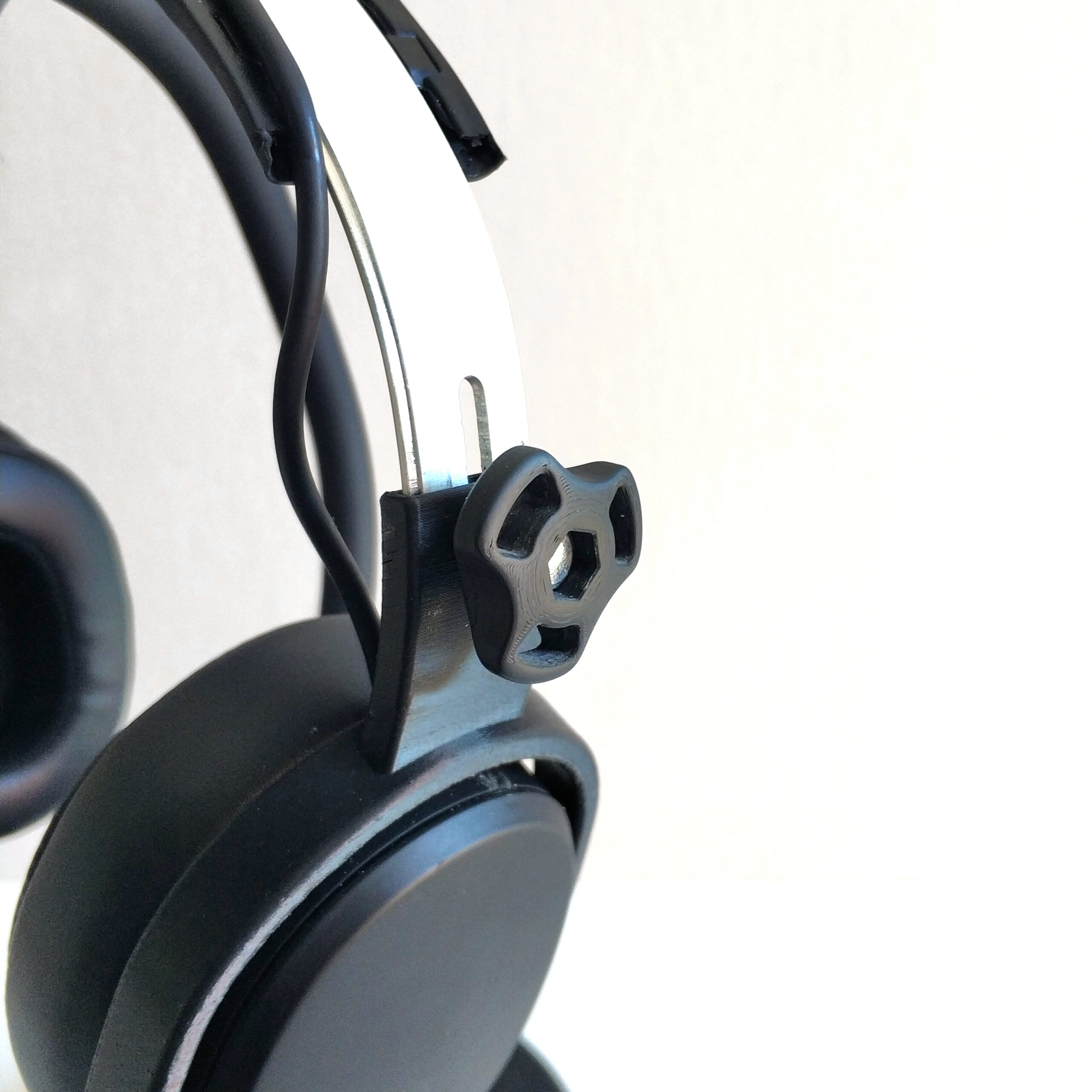
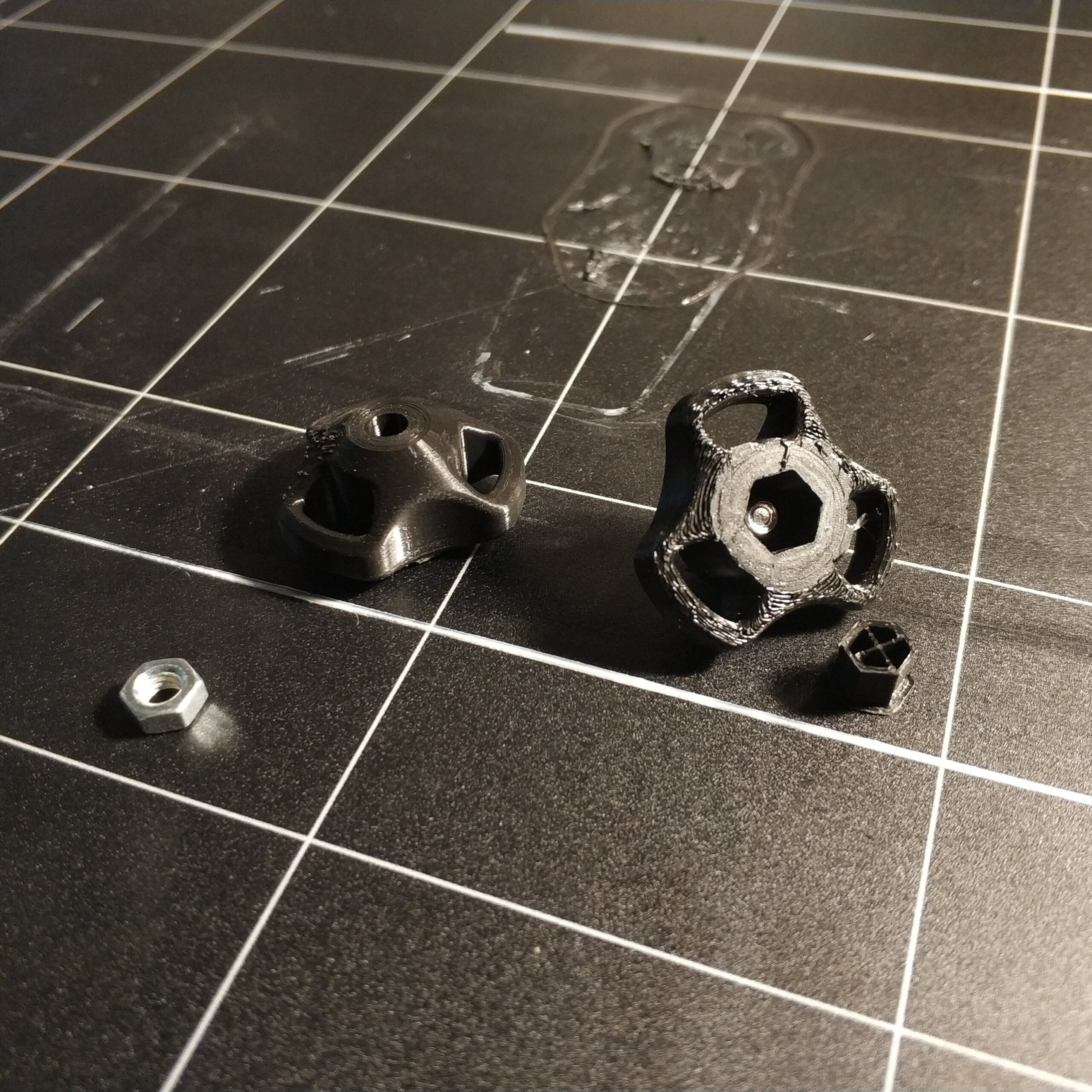
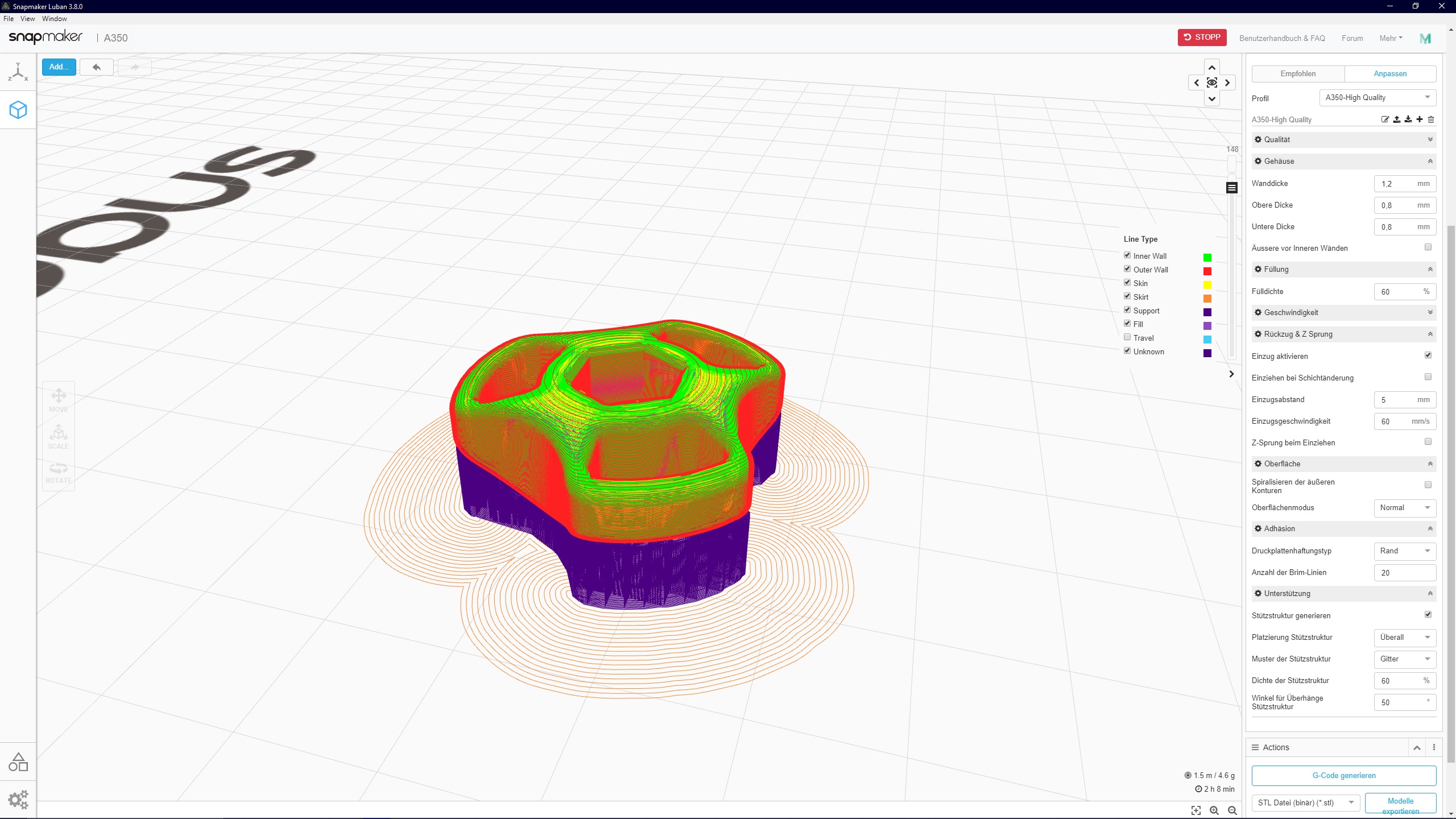
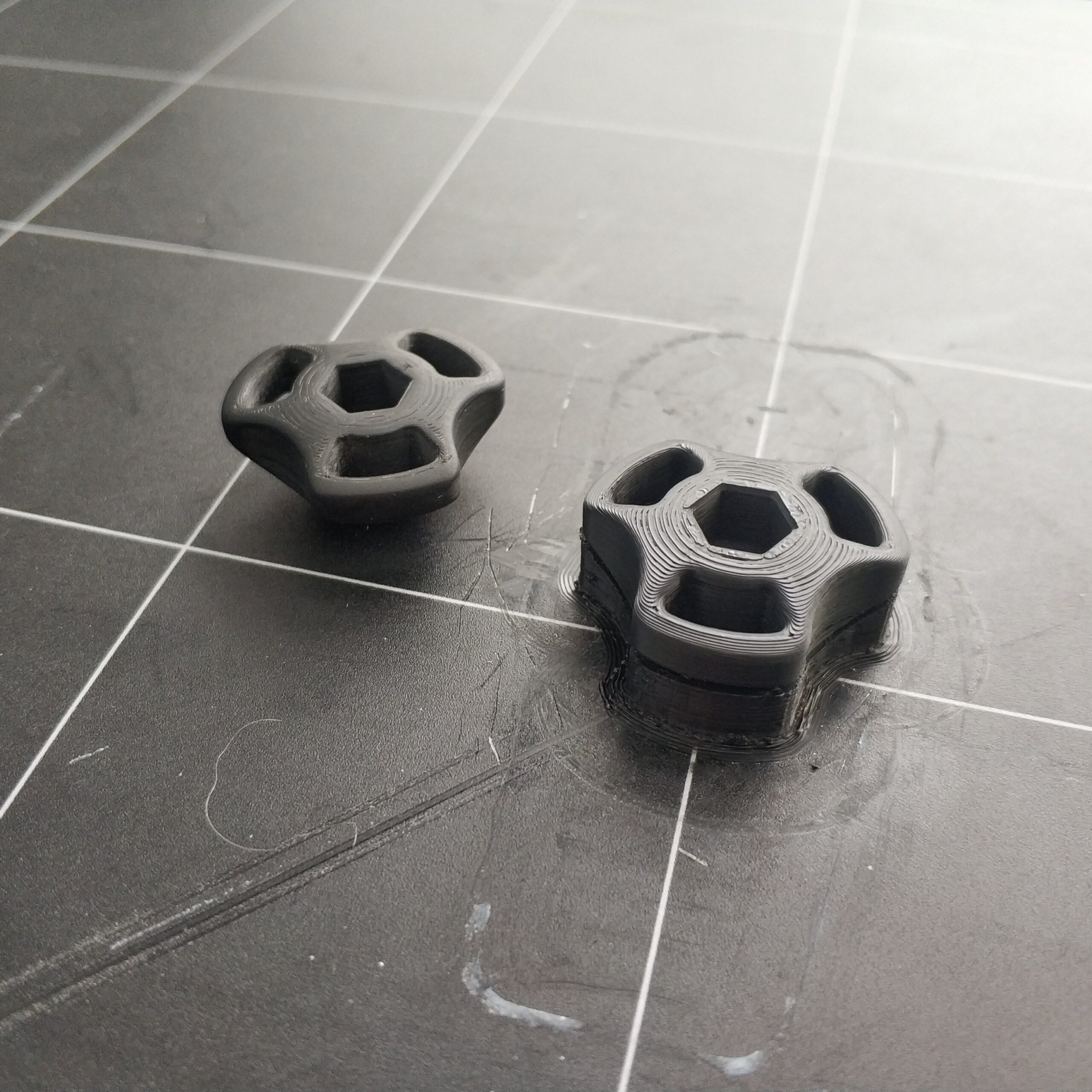
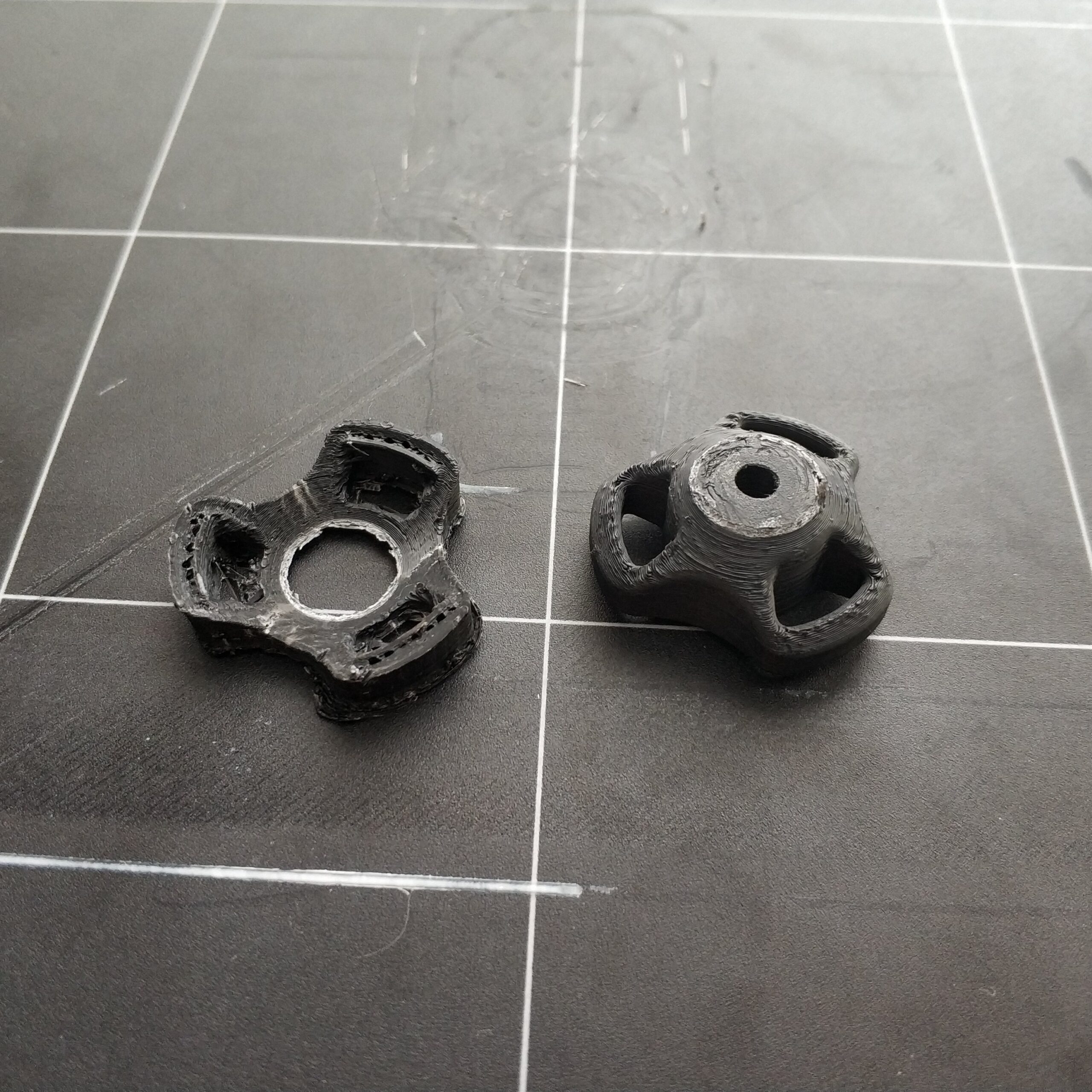
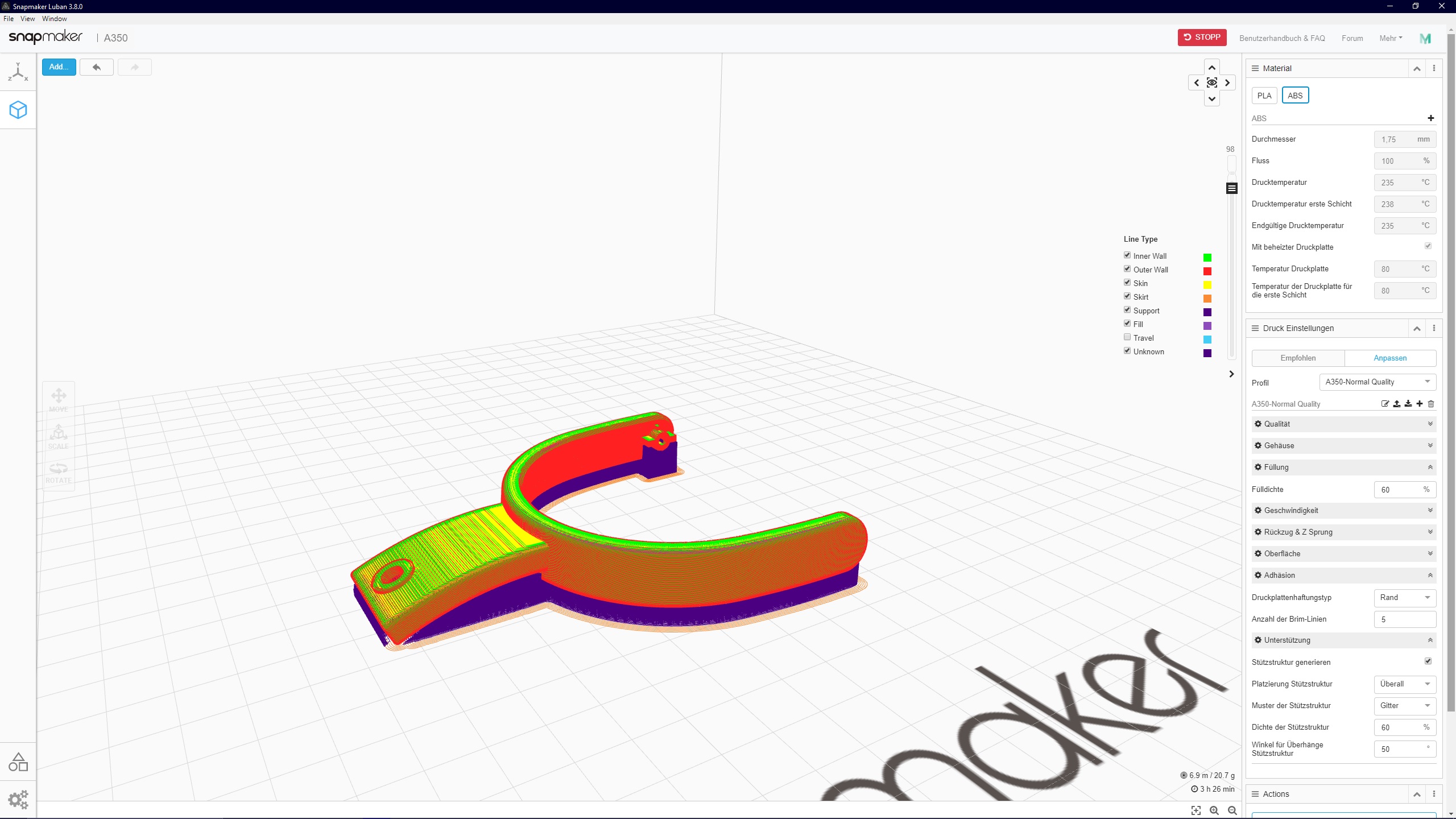
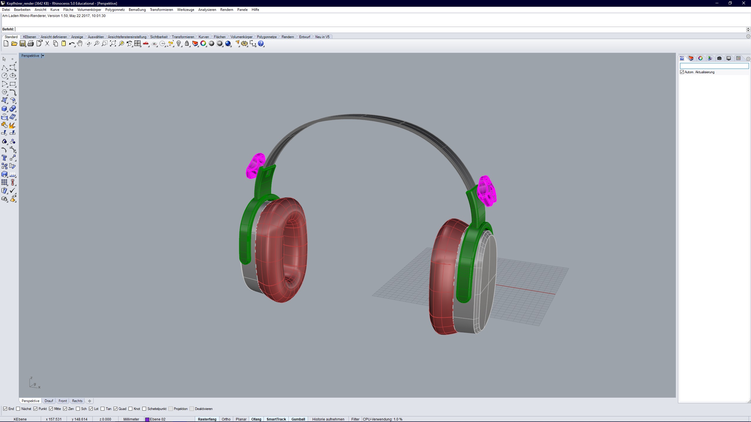
Als erstes habe ich die Drehknäufe für die höhenverstellung in CAD nach gebaut. Das original Design stammt von Valera Perinski on Thingiverse. Da Radien in Rhino schwierig sind habe ich das Model als STEP Datei gespeichert und in Fusion 360 importiert. Dort ließen sich dann leicht Radien einfügen. Wieder als STEP gespeichert habe ich das Model in Rhino reimportiert. Wenn man wollte ließen sich dann auch die Flächen und Begrenzungslinien zurückführen.
Alle Kunststoffteile des Kopfhörers sollten aus ABS sein da dieser bessere mechanische Eigenschaften haben soll als PLA. Der andere Grund war, das ich versuchen wollte die Kunststoffteile zu „vapor soothen“. Das heiß die Oberfläche des ABS durch Aceton dämpfe an zu ätzen um eine glänzende und glatte Oberfläche zu erhalten. Neben den optischen Aspekten verringert die Methode auch die Kerbbruchgefahr, da die Schichten an der Außenwand miteinander verschmelzen.
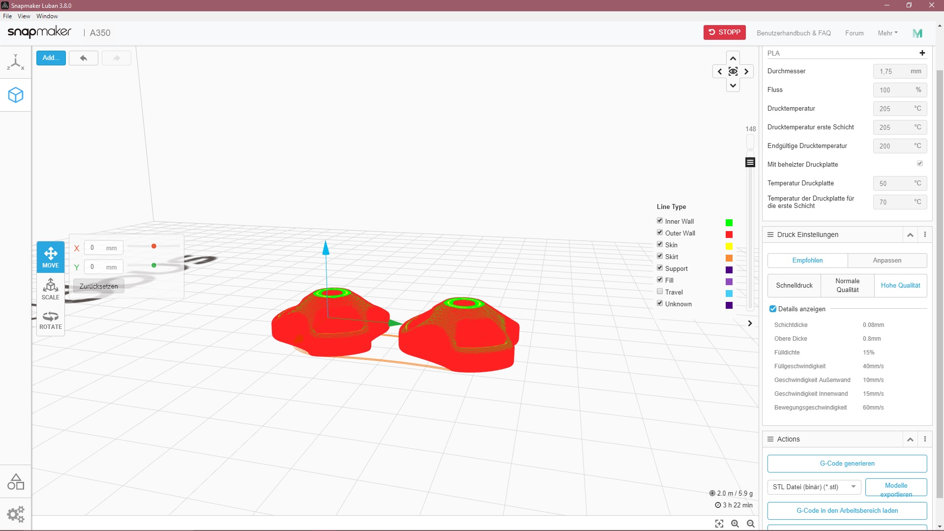
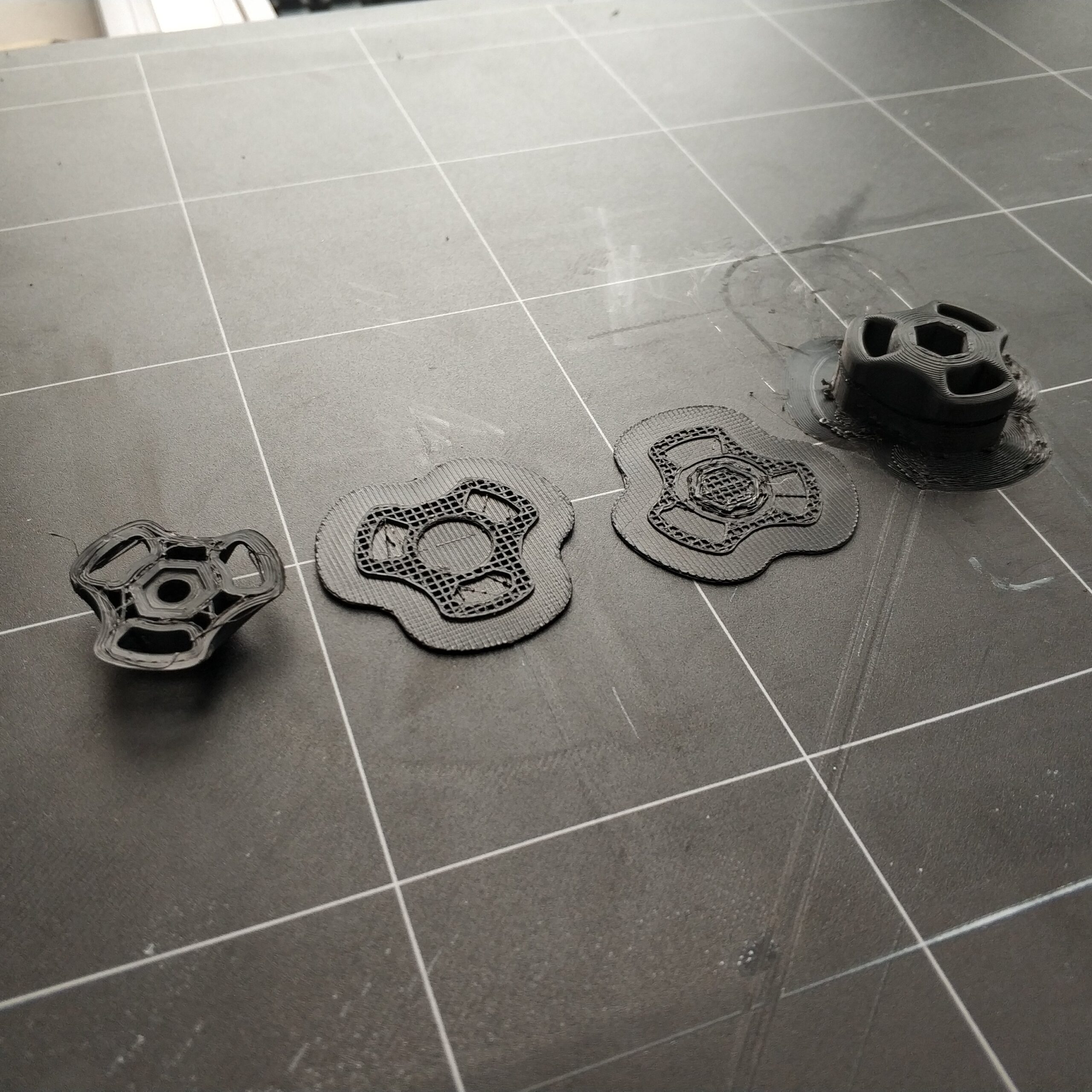
Zuerst habe ich aber die beiden Teile in PLA gedruckt um ein Gefühl für das Teil zu bekommen, da das Teil sehr flache Bereiche als auch recht große Überhänge hat. Je nach dem welche Seite oben ist können erwähnte Bereiche optisch unterschiedlich ausfallen. Dabei spielen auch Stützstrukturen und Sichtseiten eine Rolle.
Nach dem ersten Versuch habe ich mich an das ABS gewagt. Das Material ist neu für mich und hat seine Tücken. Dazu zählt auch das sich das Material verzieht durch unterschiedliche Ausdehnung bei Hitze und kälte. Das Phänomen wird in der 3D Druckwelt „warping“ genannt.
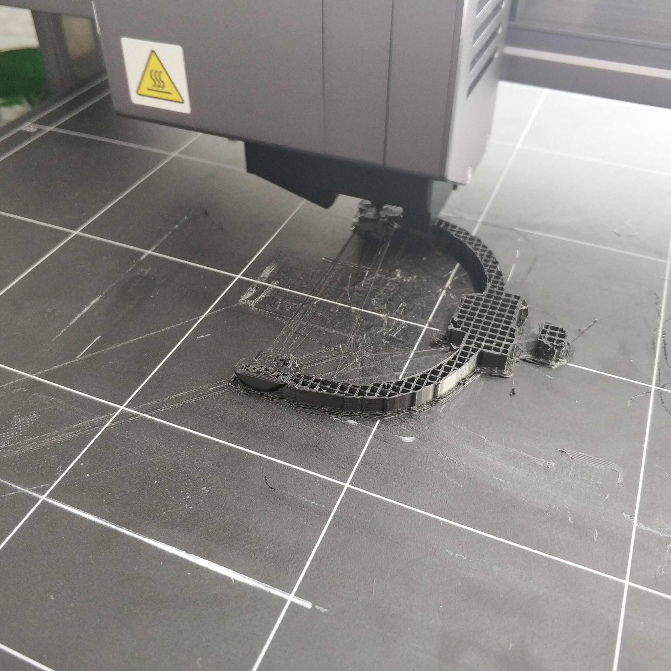
Beim ersten Versuch habe ich das Teil mit der Sichtseite nach oben ohne Stützstruktur und ohne ABS Schicht auf dem Druckbett gedruckt. Dabei hat das Teil sich bei der hälfte angefangen zu warpen und die Schichten haben nicht mehr richtig an- und aufeinander gehaftet.
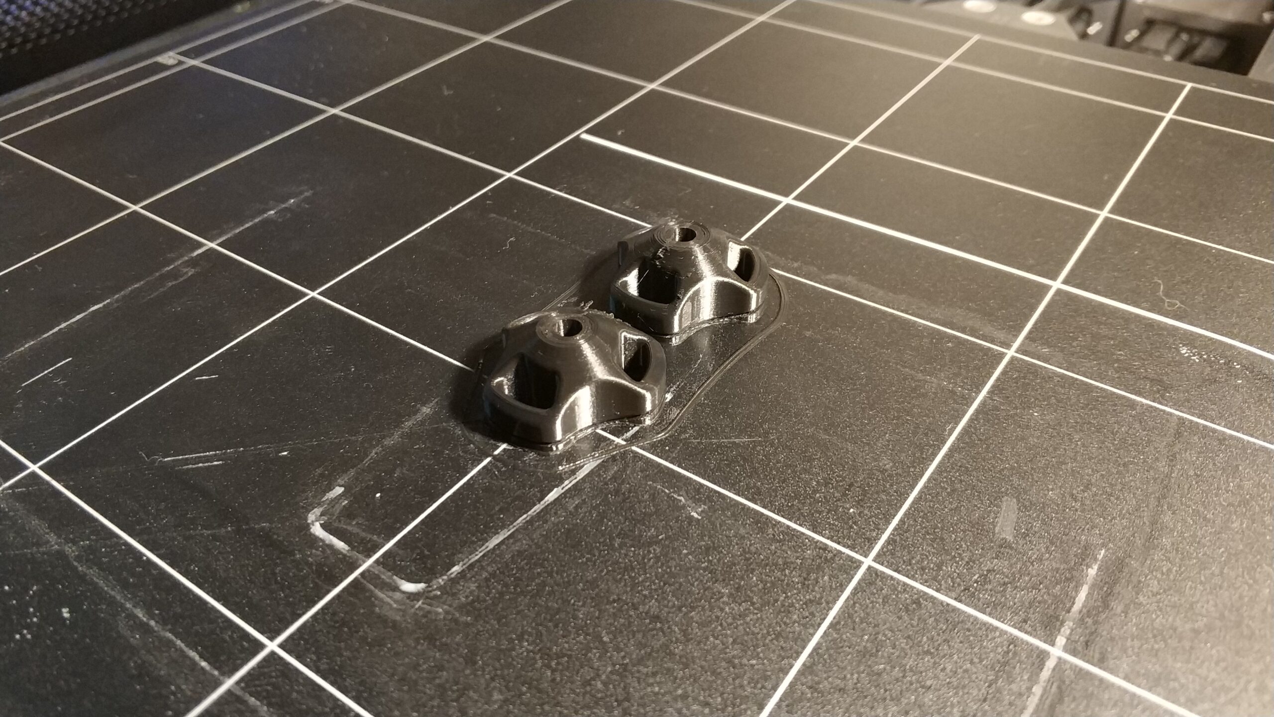
Beim zweiten und dritten Versuch habe ich mehrere ABS Schichten auf dem Druckbett drucken lassen sowie Stützstrukturen da die überhänge zu flach waren. Dabei wurden aber die ersten Schichten des eigentlichen Teil aber quasi in der Luft gedruckt und hatten keinen halt. Alle weiteren Schichten hatten dann kein Basismaterial auf dem hätte gedruckt werden können und haben nur Kunststoffsalat erzeugt. Beide Drucke wurden dann vorzeitig beendet.
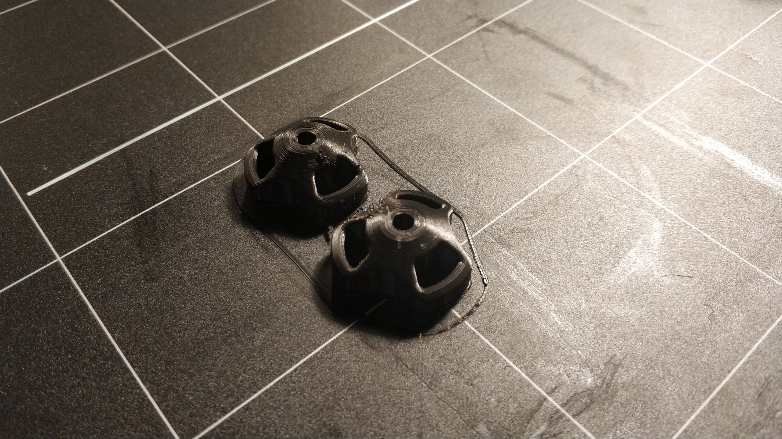
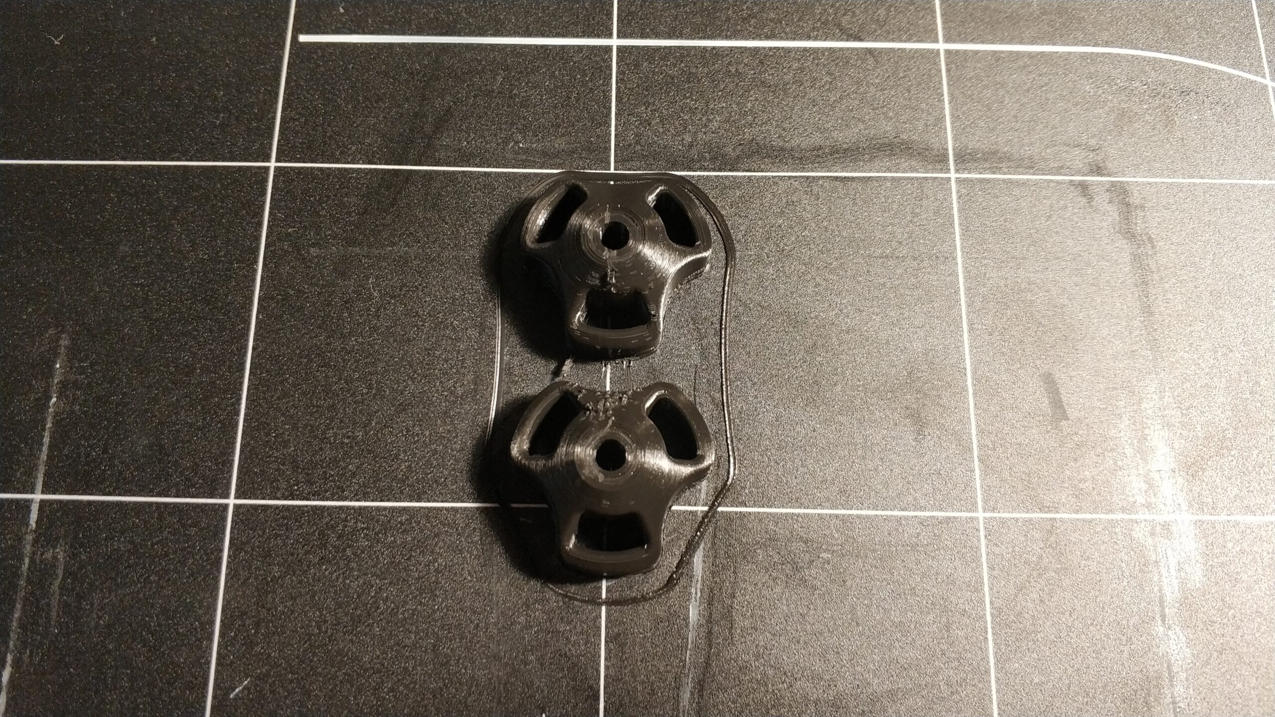
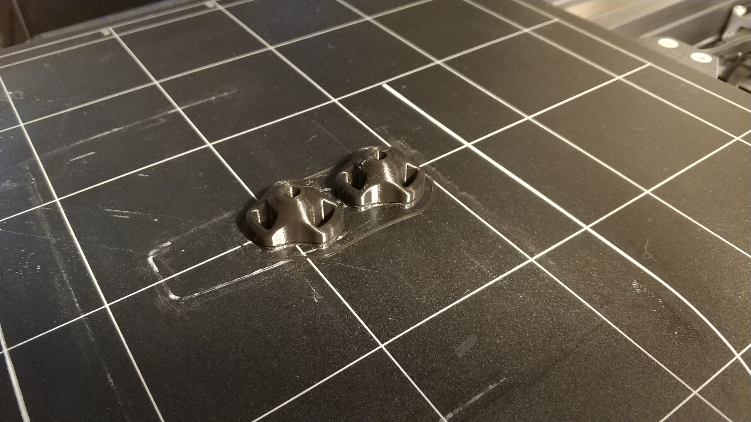
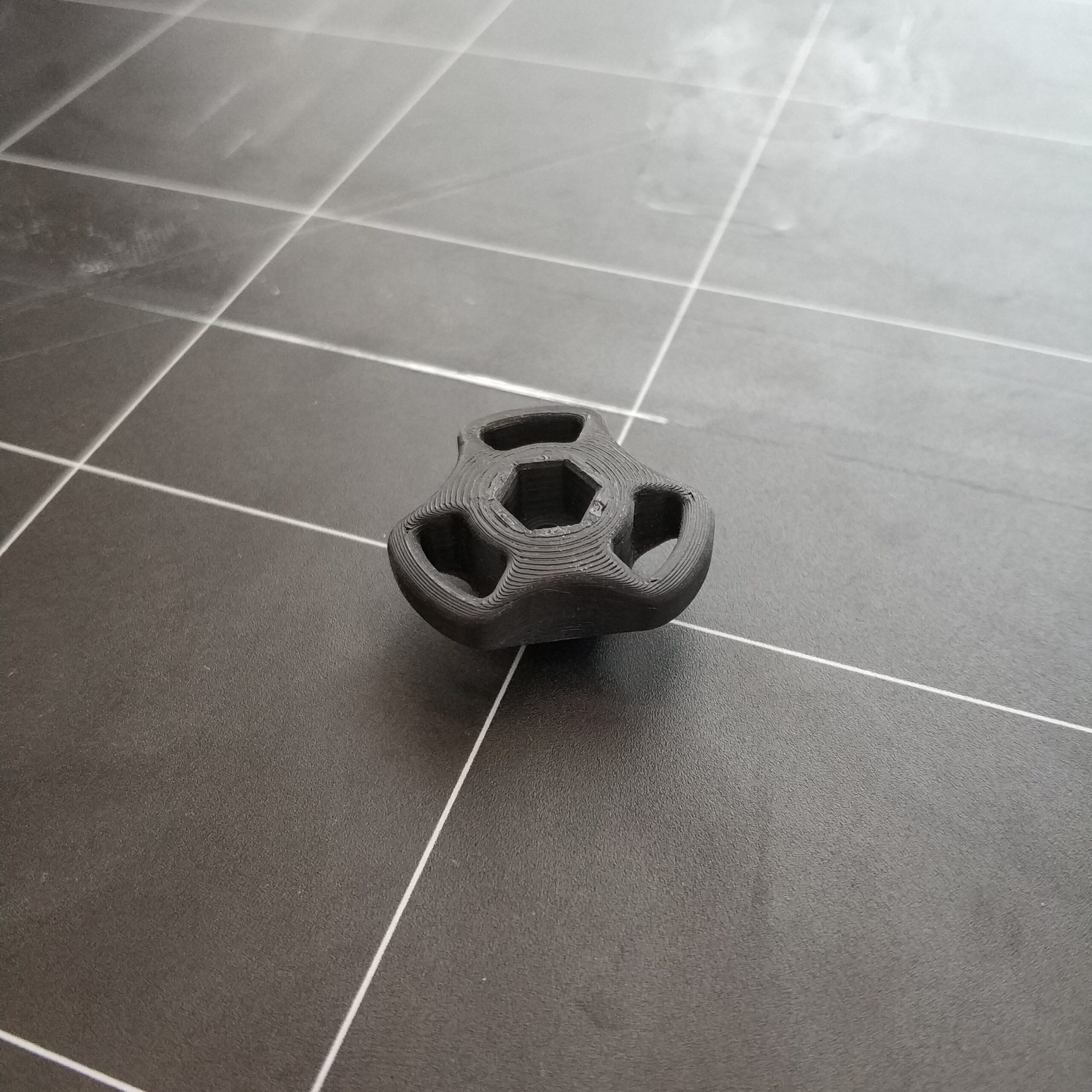
Um das Problem im nächsten Versuch zu beheben habe ich das Teil direkt auf das Druckbett platziert und für die Stützstruktur eine Lage ABS auf das Druckbett gedruckt. Das hat das Problem gelöst und hat zu einem erfolgreichem Druck geführt.
First of all, I recreated the rotary knobs for the height adjustment in CAD. The original design comes from Valera Perinski on Thingiverse. Since radii are difficult in Rhino, I saved the model as a STEP file and imported it into Fusion 360. Radii could then be easily inserted there. Once again saved as STEP, I reimported the model into Rhino. If you wanted, the surfaces and boundary lines could then be reduced.
All plastic parts of the headphones should be made of ABS because they should have better mechanical properties than PLA. The other reason was that I wanted to try to „vapor sooth“ the plastic parts. That heats the surface of the ABS to be etched by acetone fumes in order to get a shiny and smooth surface. In addition to the visual aspects, the method also reduces the risk of notch breakage, as the layers on the outer wall fuse together.
But first I printed the two parts in PLA to get a feel for the part, as the part has very flat areas as well as quite large overhangs. Depending on which side is up, the mentioned areas can look different. Support structures and visible sides also play a role here.
After the first attempt, I dared to do ABS. The material is new to me and has its pitfalls. This also includes the fact that the material warps due to different expansion in hot and cold conditions. The phenomenon is called „warping“ in the 3D printing world.
At the first attempt I printed the part face up without a support structure and without an ABS layer on the print bed. The part started to warp halfway and the layers no longer stuck together properly.
In the second and third attempt I had several ABS layers printed on the print bed as well as support structures because the overhangs were too flat. However, the first layers of the actual part were printed in the air and had no hold. All other layers then had no base material that could have been printed on and only produced plastic salad. Both prints were then terminated prematurely.
To fix the problem in the next attempt, I placed the part directly on the print bed and printed a layer of ABS on the print bed for the support structure. That solved the problem and resulted in a successful print.
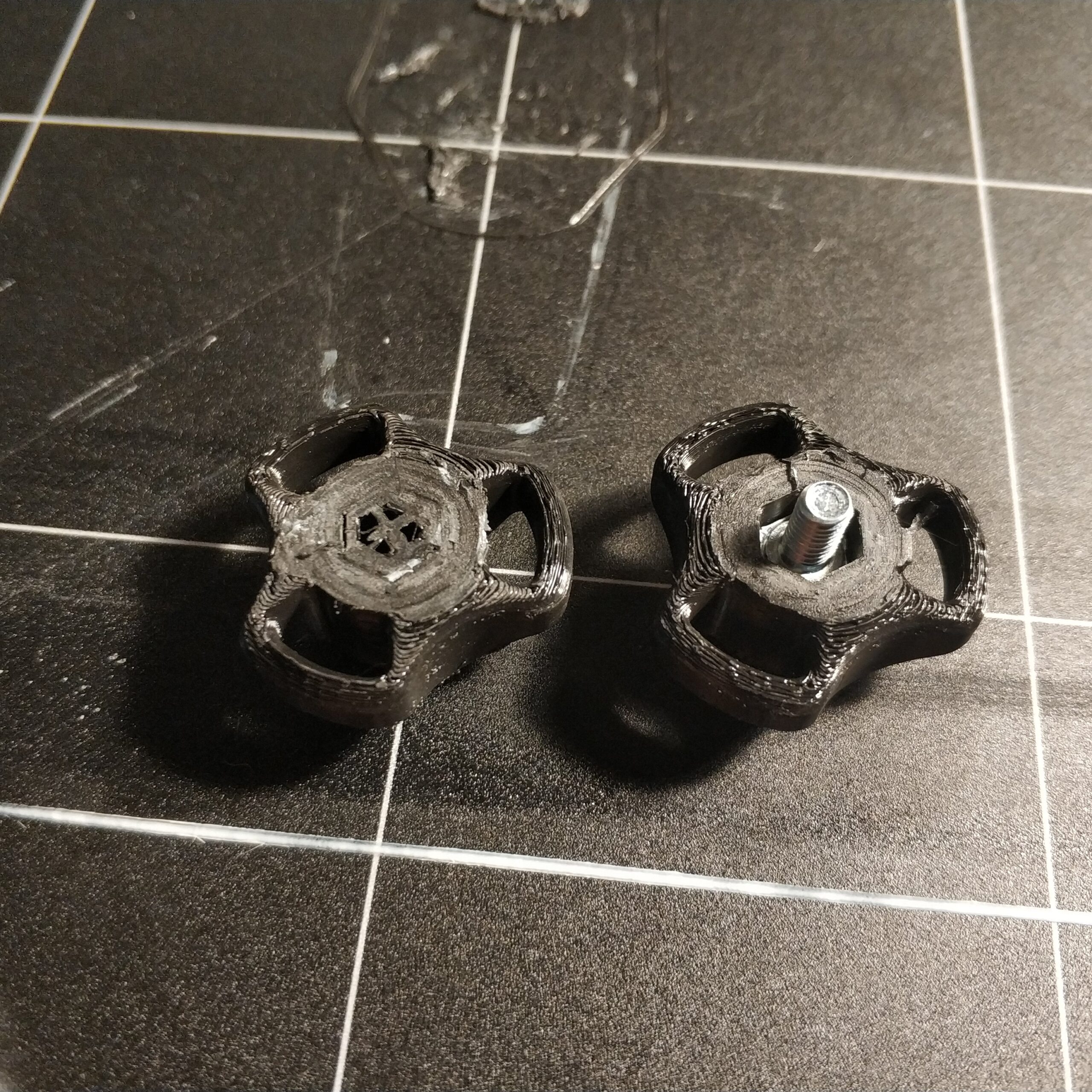
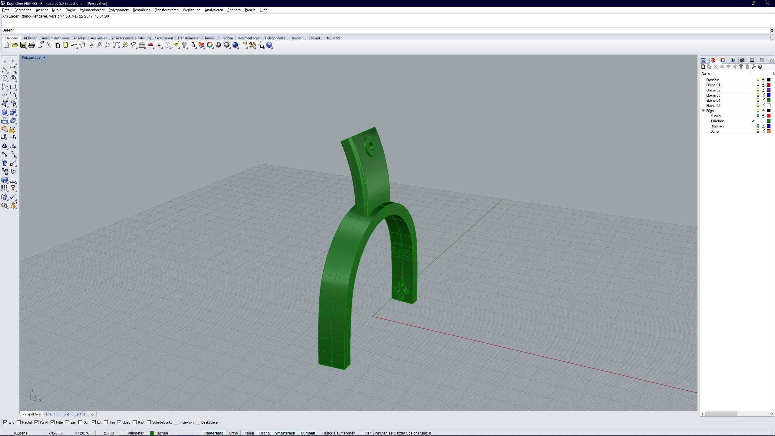
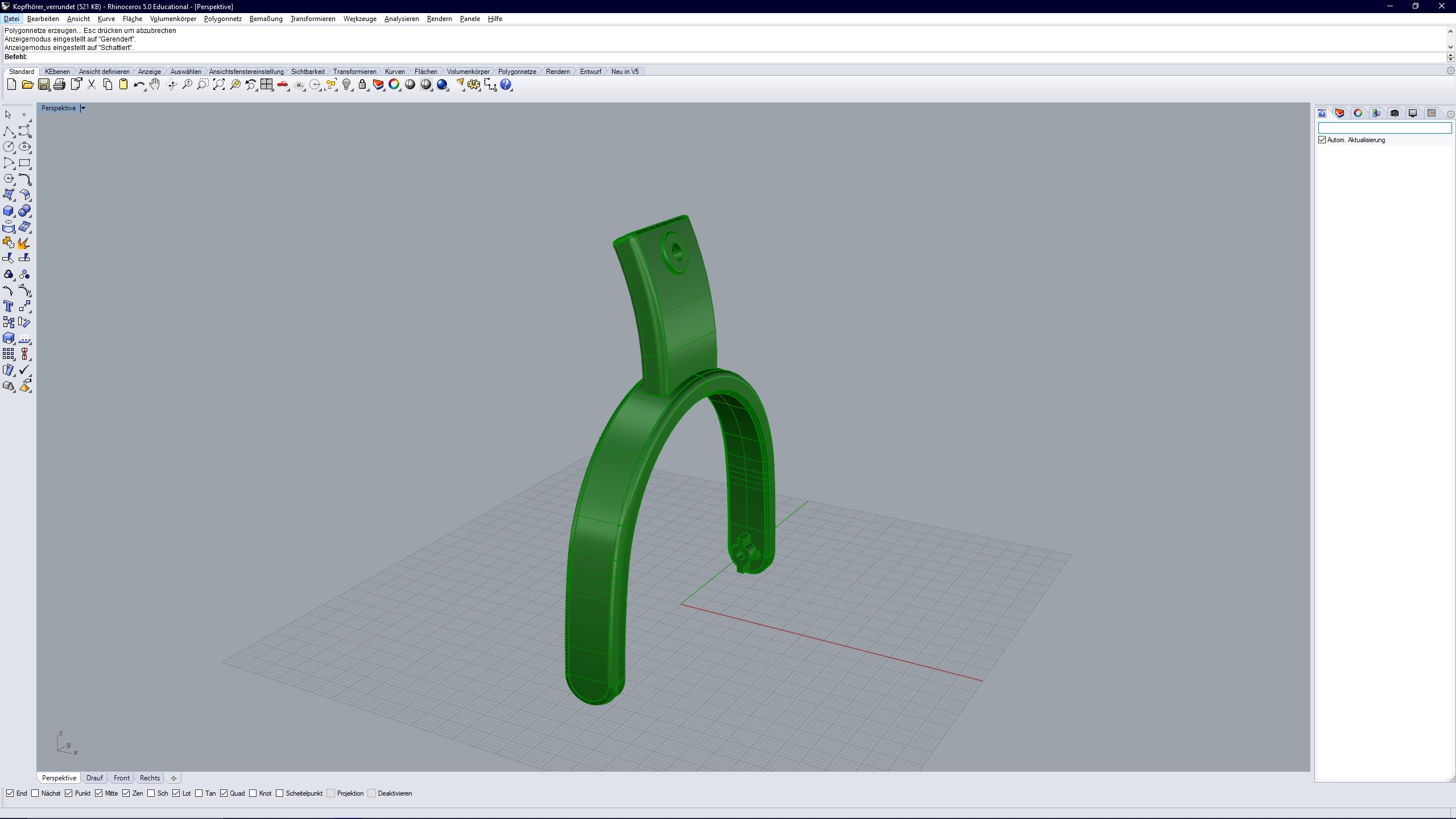
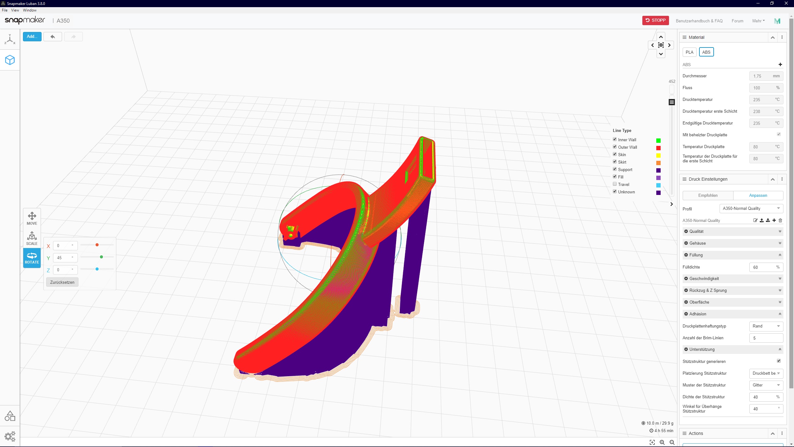
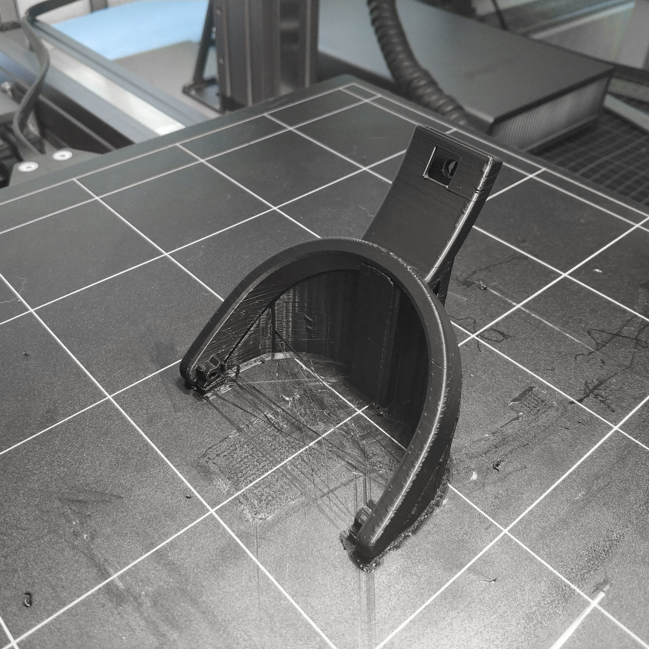
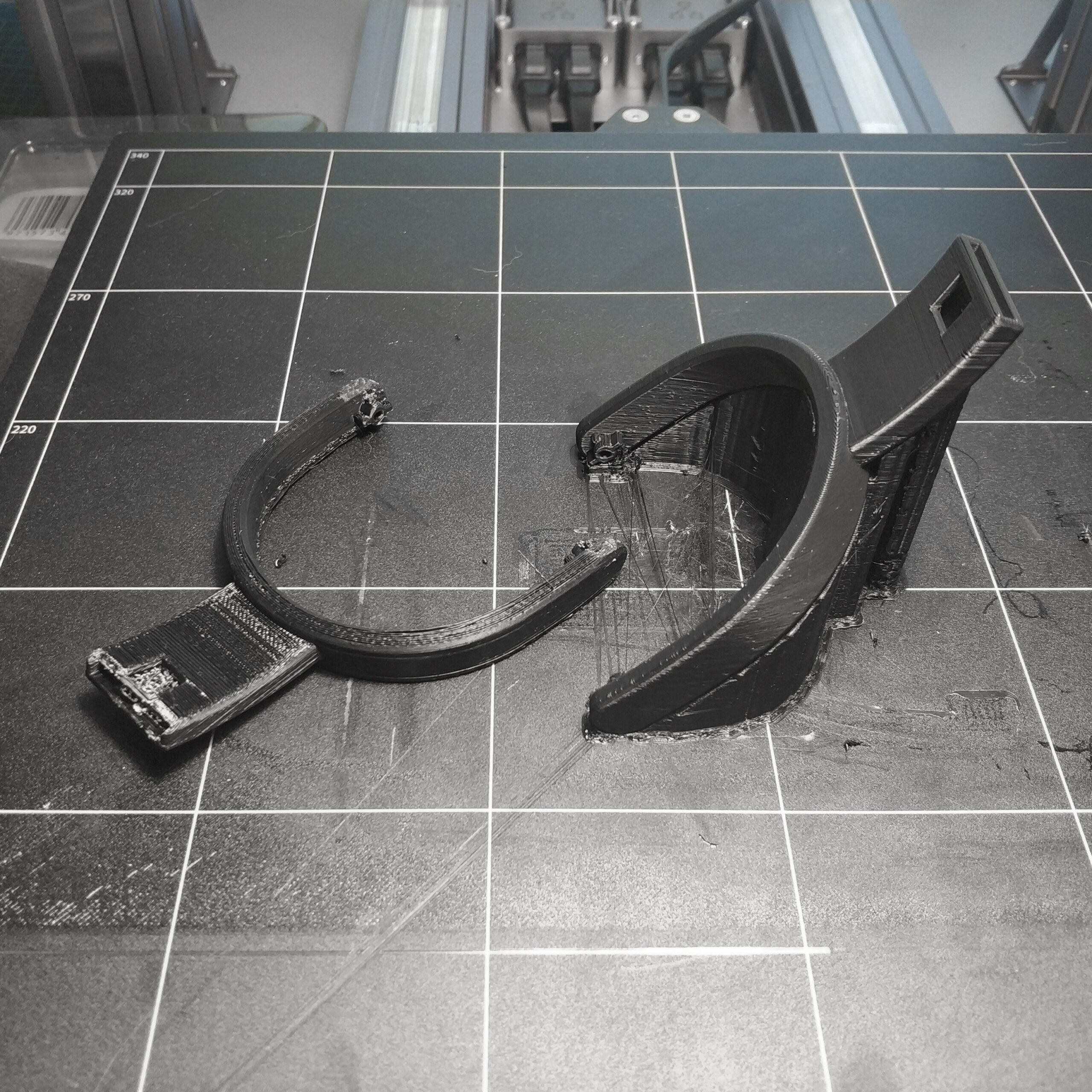
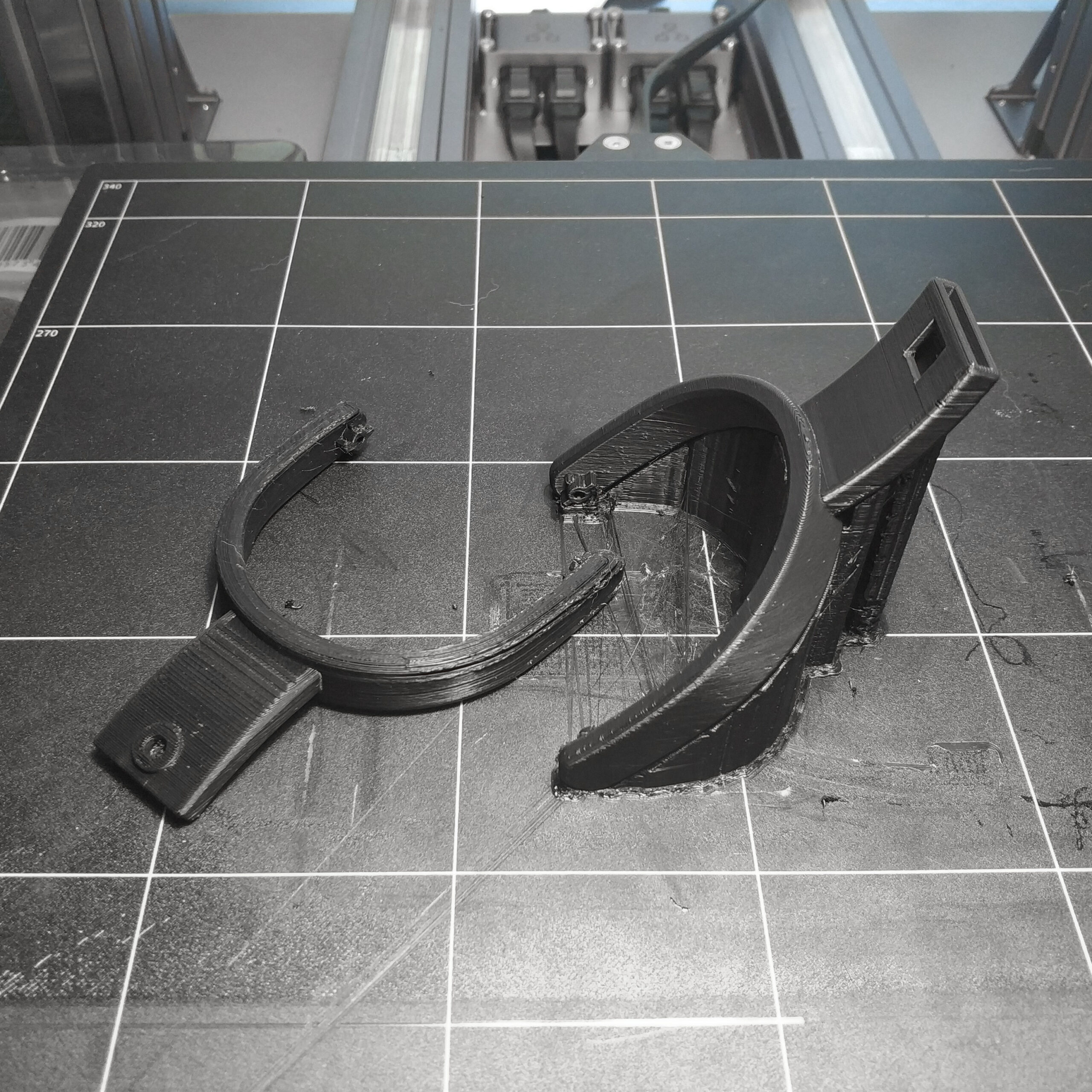
Für die Bügel habe ich die Maße des Originals genommen und in CAD nachgebaut. Nach oben hin ist eine Aussparung für ein flaches gebogenes Aluminiumteil, das die beiden Bügel miteinander verbinden soll. In dem Aluminiumteil sollen zwei Langlöcher sein um die Bügel über eine Vierkantmutter und dem Knauf mit der Schraube (M4) in der höhe zu verstellen. Die Verrundungen der Ecken habe ich wieder in Fusion 360 gemacht.
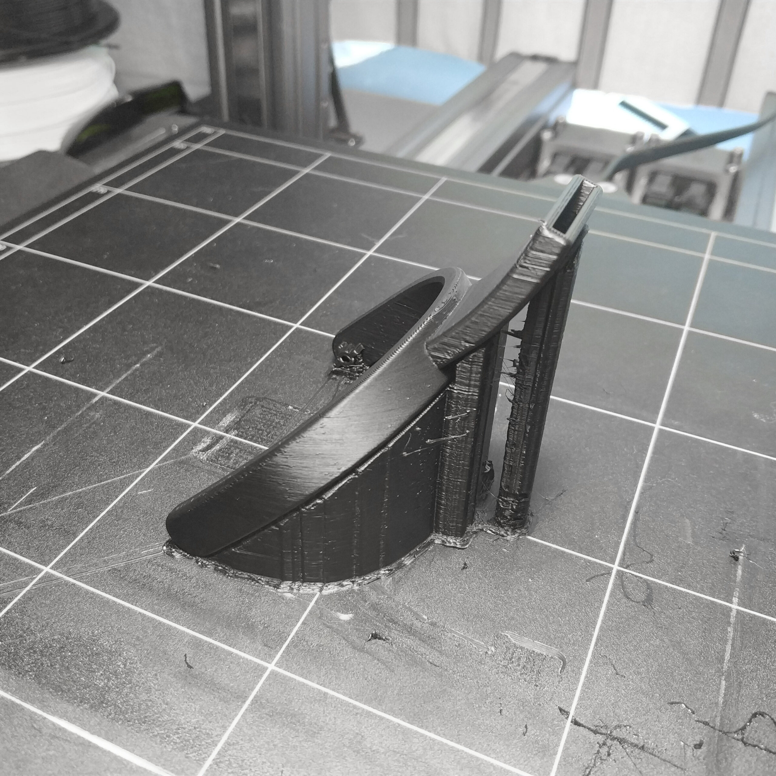
Um die Stabilität der Bügel zu maximieren wollte ich die Bügel flach auf die Grundebene legen, weil so die Schichten orthogonal zu Belastungsrichtung sind und es damit kaum zu Kerbbruch kommen kann. Leider hat das Teil sich bei ca. 3/4 angefangen nach oben zu „warpen“. Das hat dazu geführt das der Nozzel des Drückers immer in das Teil gedrückt hat und kein korrekter Schichtaufbau stattfinden konnte. Meine versuche das Teil während des Druckens am warpen zu hindern sind kläglich gescheitert. Den Grund für das warpen habe ich auf die große Querschnittsfläche und die geringe Haftung zur Stützstruktur zurückgeführt. Ein Nachteil dieser Ausrichtung war auch, das Stützstrukturen in der Aussparung für das Aluminium gedruckt wurden die Praktisch nicht zu entfernen waren. Dies und anderes soll noch mal optimiert werden wenn die jetzigen Bügel Kaputt gehen sollten oder ich nach dem Testen den drang verspüre etwas an den Bügeln zu ändern.
Um einen Kompromiss zwischen Querschnittsfläche und Kerbbruchresistenz zu finden habe ich das Teil im 45° Winkel in den Bauraum gesetzt. Das hat leider zu einer Maximierung der Menge an Stützstrukturen geführt, was sich auch negativ in der Druckzeit niedergeschlagen hat. Dennoch war der Druck recht erfolgreich, auch wenn an manchen stellen die Schichten nach unten abgesackt sind und die Stützstruktur ihre Aufgabe nicht ganz erfüllt hat.
For the hangers, I took the dimensions of the original and recreated them in CAD. Towards the top is a recess for a flat, curved aluminum part that is supposed to connect the two brackets. There should be two elongated holes in the aluminum part so that the bracket can be adjusted in height using a square nut and the knob with the screw (M4). I made the rounding of the corners in Fusion 360 again.
In order to maximize the stability of the stirrups, I wanted to lay the stirrups flat on the ground plane, because this way the layers are orthogonal to the direction of the load and there is hardly any notch breakage. Unfortunately the part started to „warp“ at about 3/4. This has led to the fact that the pin of the pusher always pressed into the part and a correct layer structure could not take place. My attempts to keep the part from warping while printing failed miserably. I attributed the reason for warping to the large cross-sectional area and the low adhesion to the support structure. A disadvantage of this alignment was that support structures were printed in the recess for the aluminum, which were practically impossible to remove. This and other things should be optimized again if the current bracket should break or I feel the urge to change something on the bracket after testing.
In order to find a compromise between cross-sectional area and notch breakage resistance, I placed the part in the installation space at a 45 ° angle. Unfortunately, this has led to a maximization of the amount of support structures, which has also had a negative impact on the printing time. Nevertheless, the print was quite successful, even if in some places the layers sagged and the support structure did not quite do its job.
Das Vapor Smoothing habe ich an dem ersten gescheiterten Druck des Bügels ausprobiert. Die glänzenden Oberflächen haben aber nicht zu den bereits vorhandenen Kunststoffteilen gepasst daher habe ich dann die 3D gedruckten Teile so gelassen wie sie sind. Die wichtigsten Erkenntnisse daraus sind, dass die Oberfläche da durch sehr glatt und glänzend werden kann aber es stark von der Methode des smoothings abhängt ob das Teil gleichmäßig und ohne Nasenbildung angeätzt wird. Hierzu möchte ich nur kurz erläutern wie ich vorgegangen bin und was ich beim nächsten mal anders machen will.
Im dem Versuch habe ich das Teil an einem Draht in ein Glasgefäß gehängt und den Boden mit etwas Aceton befüllt. Das Glasgefäß habe ich oben abgedeckt. Dann habe ich alle auf dem Herd erhitzt sodass das Aceton verdampft dabei konnte ich beobachten das der Dampf den Raum von unten nach oben langsam gefüllt hat. Daher konnte man auch schön sehen wie der Dampf erst unten am Teil und dann immer weiter nach oben am Teil kondensiert ist und es angeätzt hat. Das hat aber auch dazu geführt das der untere Teil am stärksten angeätzt war und viele Deatils verloren gegangen sind und sich auch Nasen gebildet haben durch das von oben herunterlaufende Aceton ABS Gemisch. Hingegen oben waren sogar Teilweise noch die einzelnen Schichten gut zu sehen. Das Ganze hat etwa eine halbe Stunde gedauert.
Was ich daher anders machen will ist zuerst den Raum mit Dampf zu füllen und anschließend das Teil in den Dampf zu hängen damit das Teil möglichst gleichmäßig angeätzt wird. Dabei würde es vermutlich auch reichen das Teil für weniger als 5 min vielleicht sogar nur 1-2min in den Dampf zu halten da das Ätzen eigentlich sehr schnell ging. Damit ließe sich der Prozess auch sicher stark verkürzen.
Ähnlich wie beim Lackieren ist die Oberfläche nach dem Prozess sehr Druckempfindlich und sollte daher tunlichst nicht angefasst, berührt abgelegt oder in staubiger Umgebung getrocknet werden. Wo bei ich bei dem Testteilen nach ca. 10-20 Minuten einen Drucktest gemacht habe und das Teil schon fast komplett durchgehärtet war. Dennoch waren kleine druckspuren zu sehen aber nur weil ich es auch darauf angelegt habe. Ich könnte mir vorstellen das man schon nach 2-3 Stunden auf der sicheren Seite ist und Teile weiter verarbeiten kann.
Beim Lackieren sollte man übrigens mindestens 6-8 Stunden, am besten 12 Stunden warten.
Der Sprühdosen Lack mit dem ich noch nie schlechte Erfahrungen gemacht habe ist von der Marke „Molotow“.
Und bloß keinen Wasserbasierten Lack, da tut man der Umwelt nämlich nichts wirklich was gutes und einem selbst auch nicht, da der sich wie der Name verrät in Wasser löst aus dem man aber auch zu 90% besteht. Daher kann der Körper das auch super über die Haut und ggf. die Schleimhäute aufnehmen.
I tried the vapor smoothing on the first failed pressure of the bracket. The shiny surfaces didn’t match the existing plastic parts, so I left the 3D printed parts as they are. The most important findings from this are that the surface can become very smooth and shiny as a result, but whether the part is etched evenly and without the formation of a nose strongly depends on the method of smoothing. I would just like to briefly explain how I proceeded and what I want to do differently next time.
In the experiment I hung the part on a wire in a glass vessel and filled the bottom with a little acetone. I covered the top of the glass vessel. Then I heated them all on the stove so that the acetone evaporated and I could see that the steam slowly filled the room from bottom to top. Therefore you could see how the steam first condensed at the bottom of the part and then further and further up the part and etched it. However, this also led to the lower part being most heavily etched and many details have been lost and noses have also formed due to the acetone ABS mixture running down from above. On the other hand, some of the individual layers were still clearly visible at the top. The whole thing took about half an hour.
What I want to do differently is to first fill the room with steam and then hang the part in the steam so that the part is etched as evenly as possible. It would probably be enough to hold the part in the steam for less than 5 minutes, maybe even only 1-2 minutes, since the etching was actually very fast. This would certainly shorten the process considerably.
Similar to painting, the surface is very sensitive to pressure after the process and should therefore not be touched, stored or dried in a dusty environment. Where I did a pressure test on the test parts after about 10-20 minutes and the part was almost completely cured. Nevertheless, there were small pressure marks, but only because I put it on them. I could imagine that after 2-3 hours you are on the safe side and can continue processing parts.
By the way, when painting you should wait at least 6-8 hours, preferably 12 hours.
The spray paint with which I have never had bad experiences is from the brand „Molotow“.
And just no water-based paint, because you are not doing anything really good for the environment and you are not doing anything to yourself either, because as the name suggests, it dissolves in water, which is also 90% made of. Therefore, the body can absorb this super through the skin and possibly the mucous membrane.
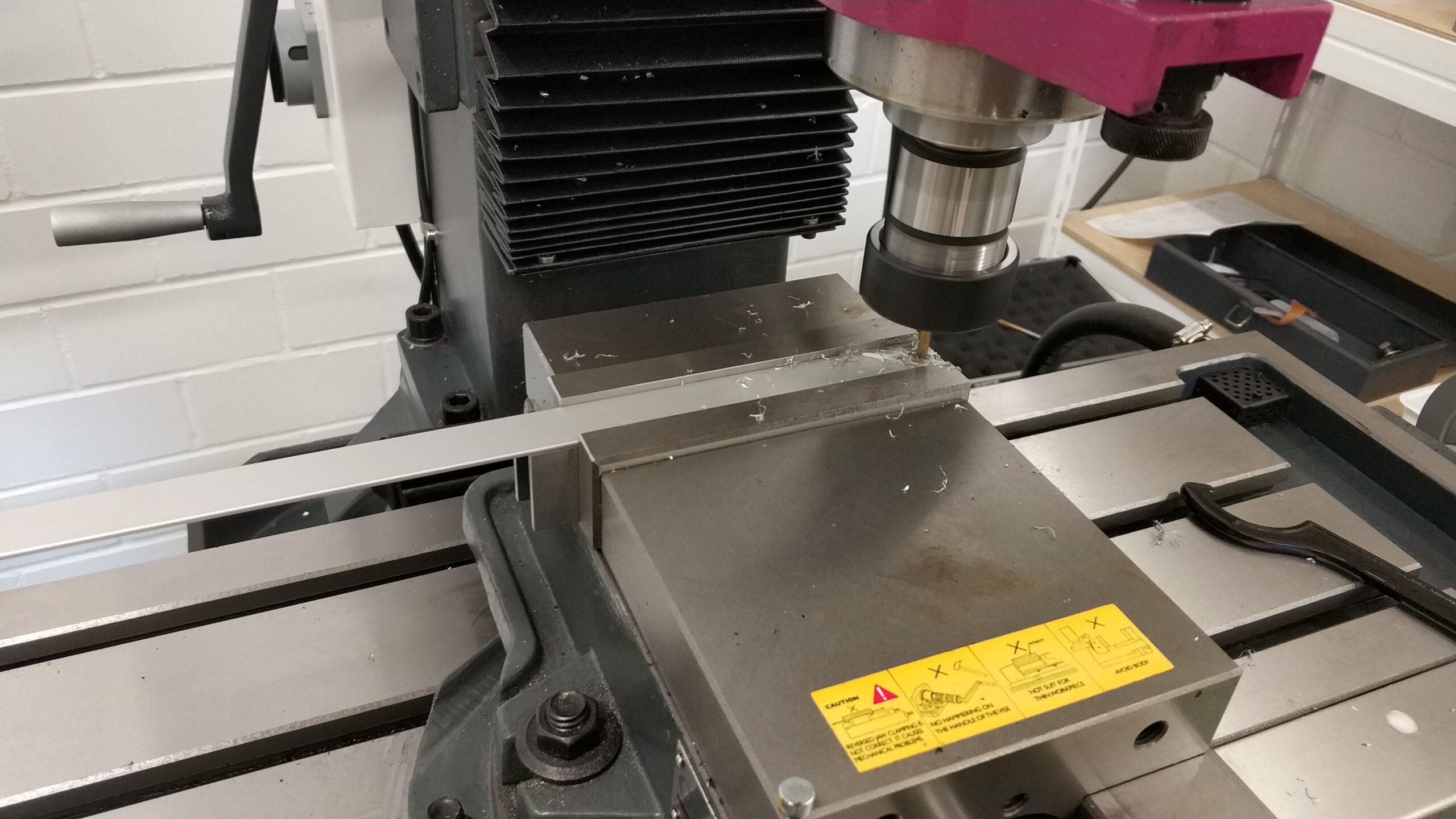
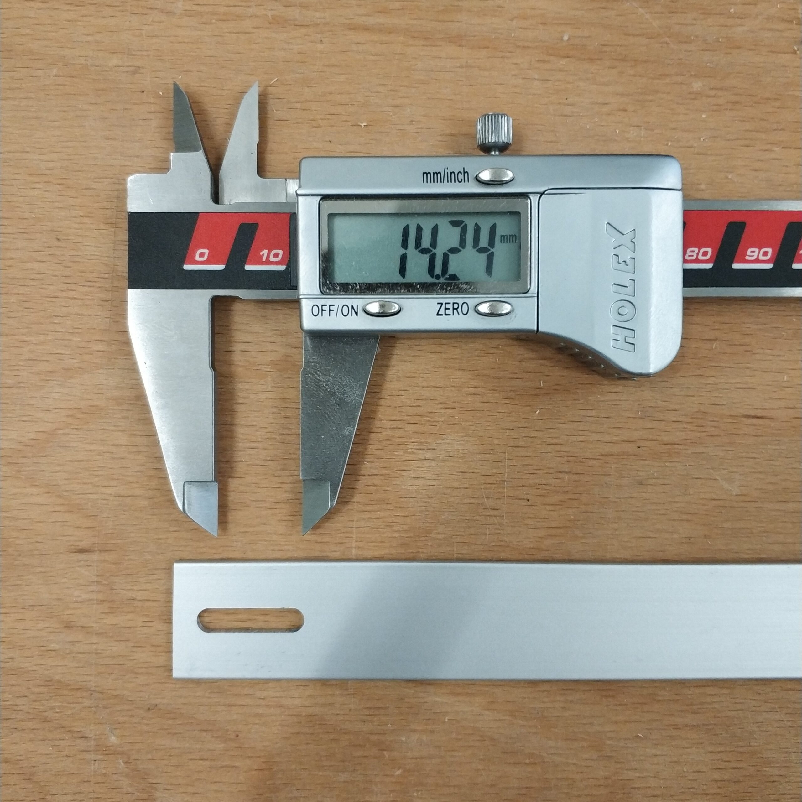
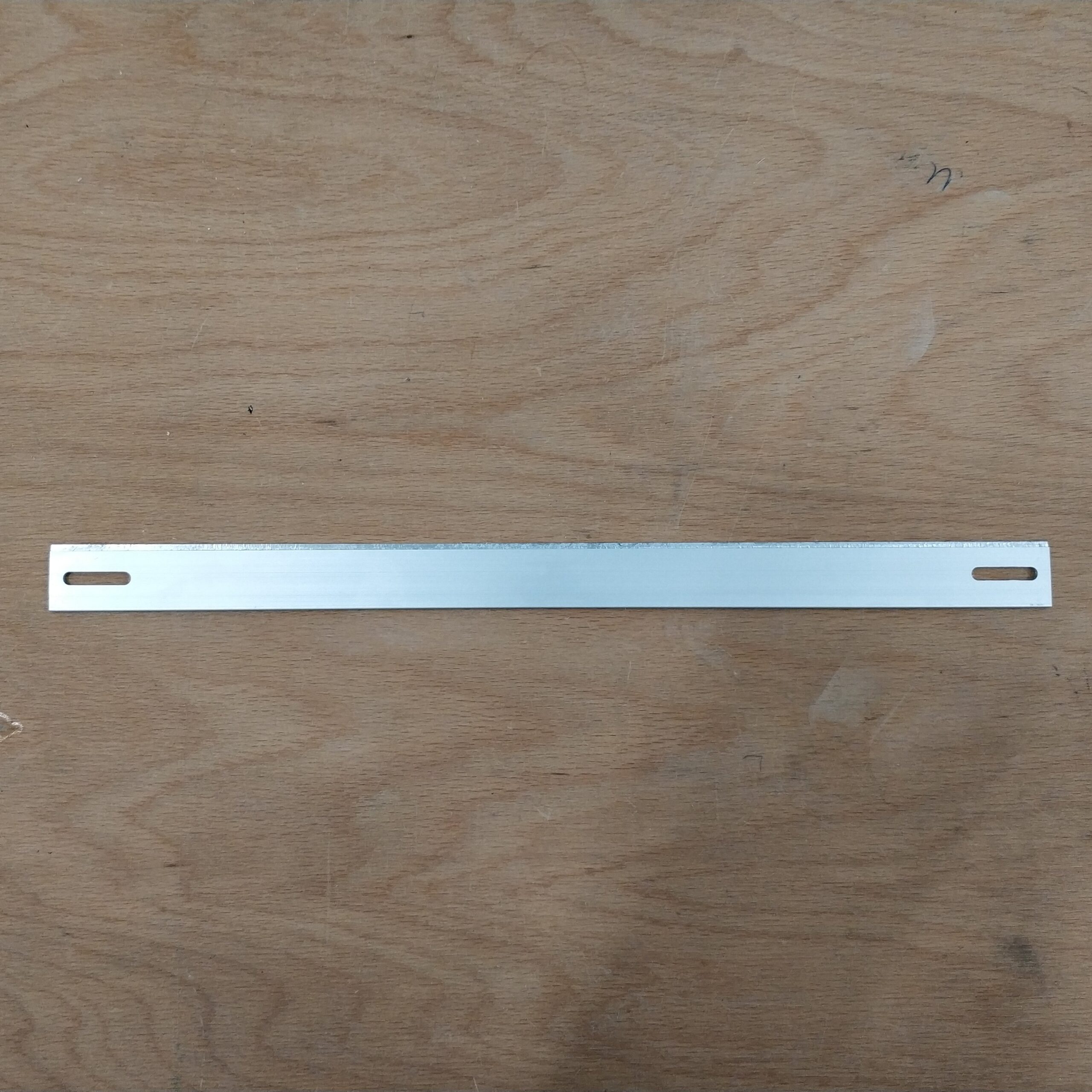
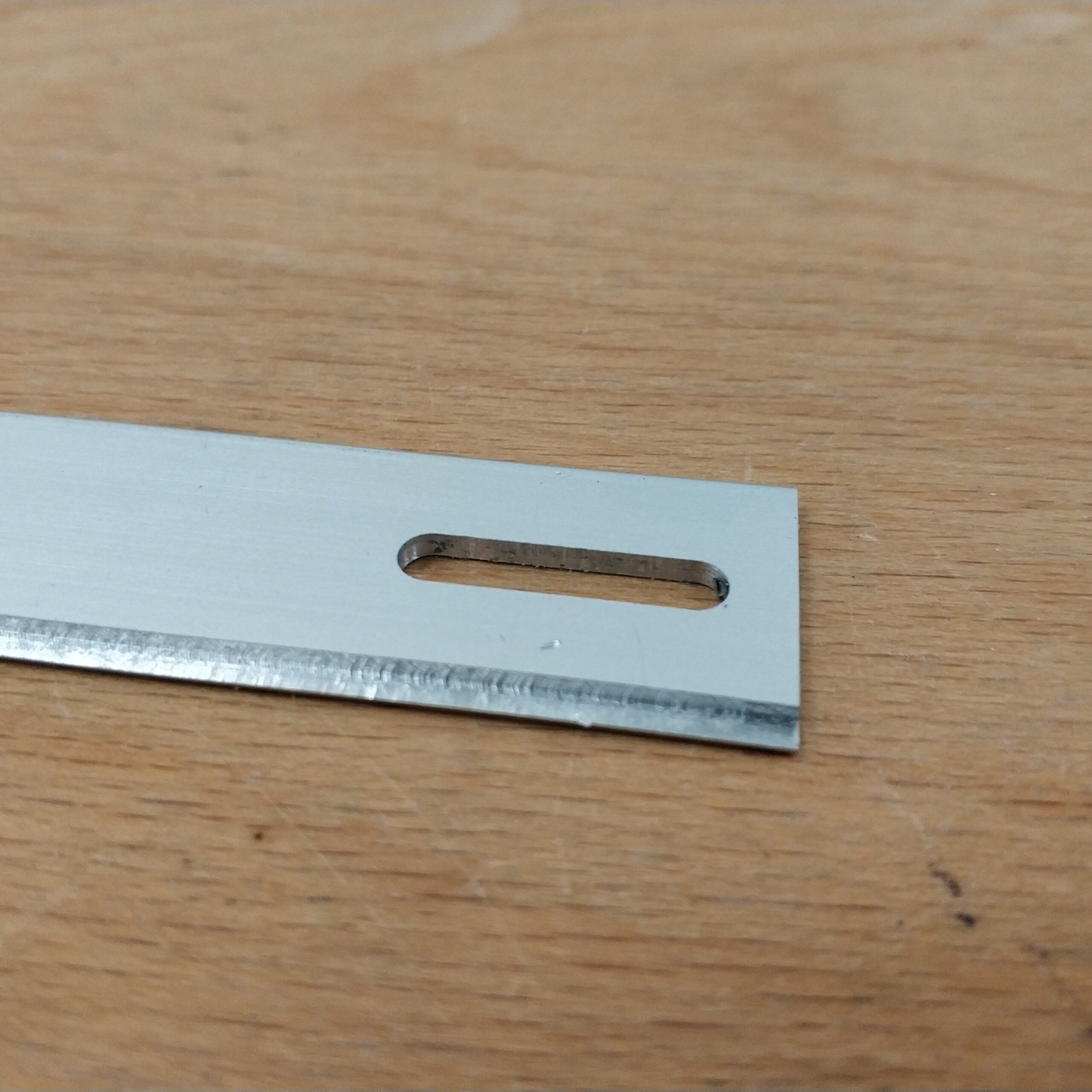
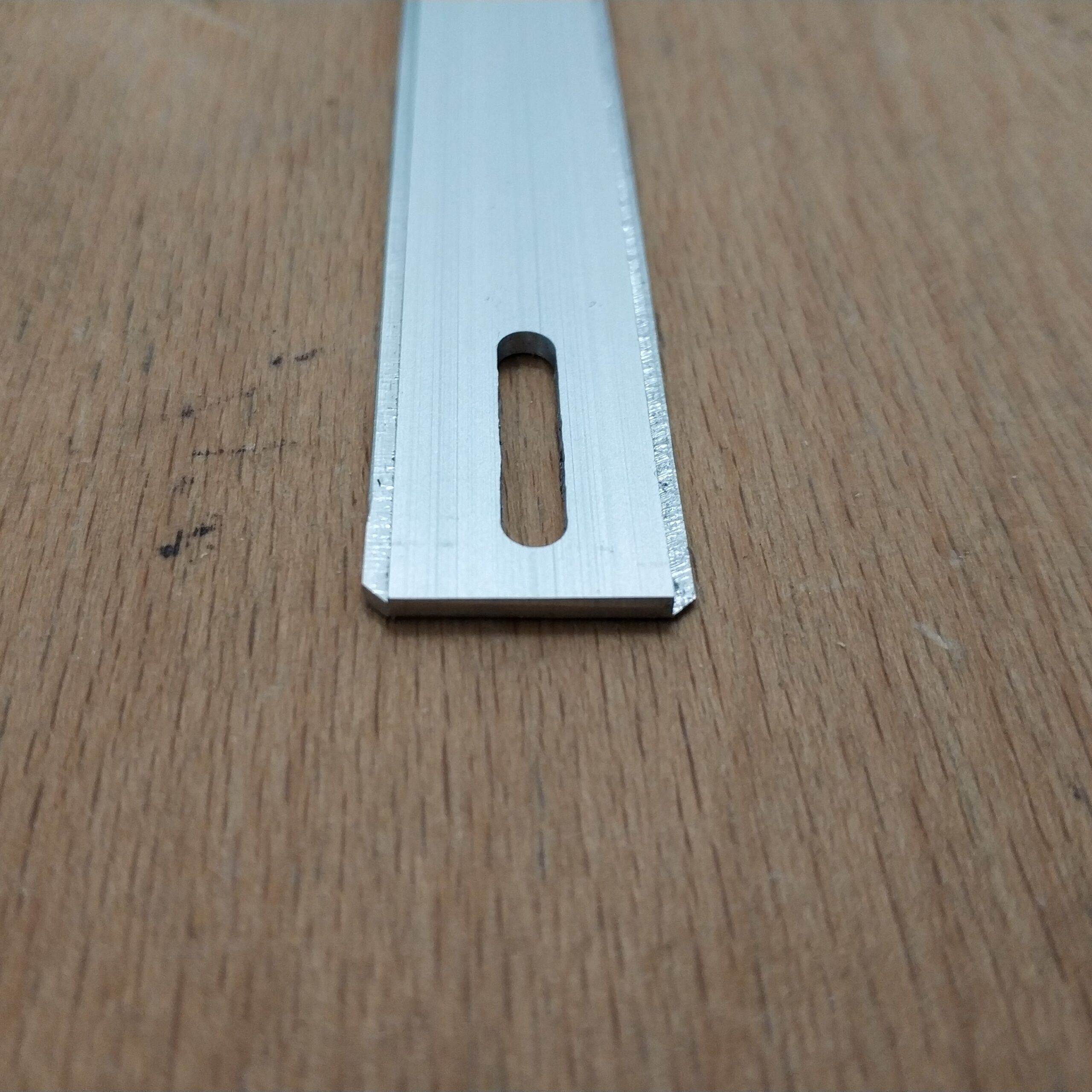
Das Verwendete Aluminium habe ich als Reststücke bei einem hiesigen Online Händler bestellt und Vorort abgeholt. Kosten dafür waren ca. 4€. Ich habe einmal ein Stück eloxiertes Aluminium und einmal normales Aluminium bestellt. Die Maße sind 2mm x 20mm. Um die richtige Länge zu ermitteln habe ich ein Stück Pappe zurecht geschnitten und über meinen Kopf gebogen. Dabei kamen Längen zwischen 28-32cm her raus. Ich habe dann die Mitte 30cm genommen und das Aluminium mit einer Trennscheibe und einem elektrischen Multitool gekürzt.
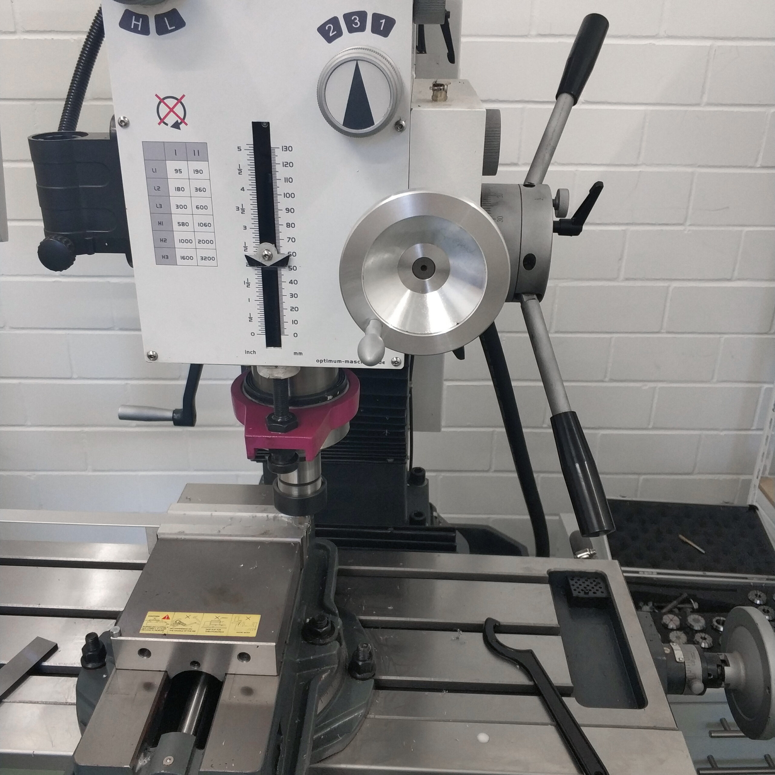
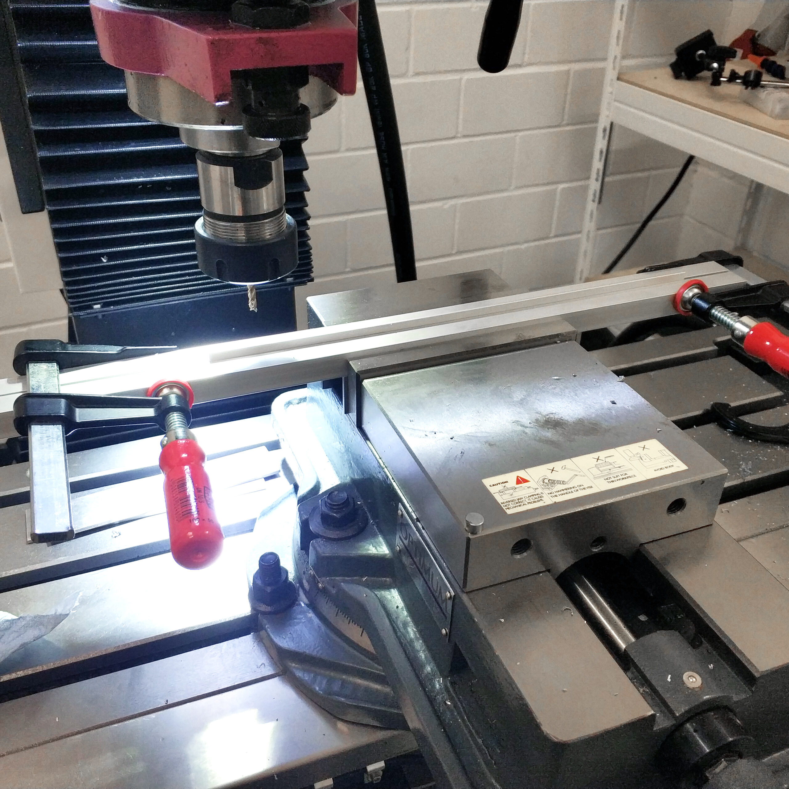
Die Langlöcher wurden auf einer großen Fräse mit einem 4mm Z4 Fräser bei 1600rpm gefräst.
Um später das Kopfpolster anbringen zu können mussten auf beiden Seiten etwas weggefräst werden. Da der Schraubstock zu kurz war habe ich das Teil zwischen zwei Aluminium Vierkantrohre eingeklemmt. Mit dem zum glück vorhandenen automatischen Vorschub konnte ich alles zügig fräsen. Wobei der Vorschub vielleicht etwas schnell war. Ein Problem war auch das über die Länge von links zu rechts eine Differenz in Y von etwa 0,5mm war, was bei der Stärke von 2mm und einem geplanten Abtrag von 1mm an einem Ende zu einer unangenehmen schneide geführt hat. Das ganze habe ich aber als nicht so schlimm erachtet da die Enden eh in den Kunststoffbügeln versteckt sind. Beim zweiten Fräsen habe ich das ganze versucht etwas auszugleichen durch einen Versatz von 0,25mm. Am Ende habe Ich noch die Ecken gefast und die langen Seiten etwas entgratet.
Zum biegen des Aluminiums war der neu Ikea Mörser sehr hilfreich um dessen Außenmantel ich es nach und nach gebogen habe. Am Ende hat es dann auch noch etwas Zangengewalt gebraucht.
Die Kaputten Ohrpolster wurden durch neue über das Internet bestellte ersetzt. Die Polster waren am teuersten mit etwa 18€.
Der Zusammenbau war danach eigentlich trivial.
Was noch fehlt sind ein par Halter für das Kabel welches im Moment noch recht lose über den Aluminiumbügel geführt wird.
I ordered the used aluminum as leftover pieces from a local online dealer and picked it up on site. The cost for this was around € 4. I ordered a piece of anodized aluminum once and normal aluminum once. The dimensions are 2mm x 20mm. To find the right length, I cut a piece of cardboard and bent it over my head. Lengths between 28-32cm came out. I then took the middle 30cm and shortened the aluminum with a cutting disc and an electric multitool.
The elongated holes were milled on a large milling machine with a 4mm Z4 milling cutter at 1600rpm.
In order to be able to attach the head cushion later, something had to be milled away on both sides. Since the vice was too short, I clamped the part between two aluminum square tubes. With the luckily available automatic feed, I was able to mill everything quickly. Although the advance was perhaps a bit fast. Another problem was that there was a difference in Y of about 0.5mm over the length from left to right, which led to an uncomfortable cutting edge with a thickness of 2mm and a planned removal of 1mm at one end. I didn’t think the whole thing was that bad because the ends are hidden in the plastic brackets anyway. During the second milling I tried to compensate for the whole thing a bit by an offset of 0.25mm. At the end I chamfered the corners and deburred the long sides a bit.
To bend the aluminum, the new Ikea mortar was very helpful, around the outer shell of which I gradually bent it. In the end, it also took some force of pincer.
The broken ear pads were replaced with new ones ordered online. The cushions were the most expensive at around € 18.
The assembly afterwards was actually trivial.
What is still missing are a couple of brackets for the cable which at the moment is still quite loosely guided over the aluminum bracket.