Projekte
Projects
Schwibbogen - Umrüstung Glühbirne zu LED
Schwibbogen - conversion of lightbulbs to LED
12.2020
Überblick
Overview
Geplantes Budget
planed budget
Fortschritt
progress
Design
Prepare
Build
Test
Done!
Maschienen und Werkzeuge
Machines and tools
Ein fast schon uralter Schwibbogen, von Ikea, aus der Ära der Glühbirnen braucht schon seit Jahren eine Umrüstung auf LEDs, da eine Glühbirne nach der anderen den Geist aufgegeben hat und Ersatz nicht mehr zu bekommen ist.
Der Beginn der Weihnachtszeit hat mir den Impuls gegeben nicht noch ein Jahr ins Land ziehen zu lassen und das Projekt umzusetzen.
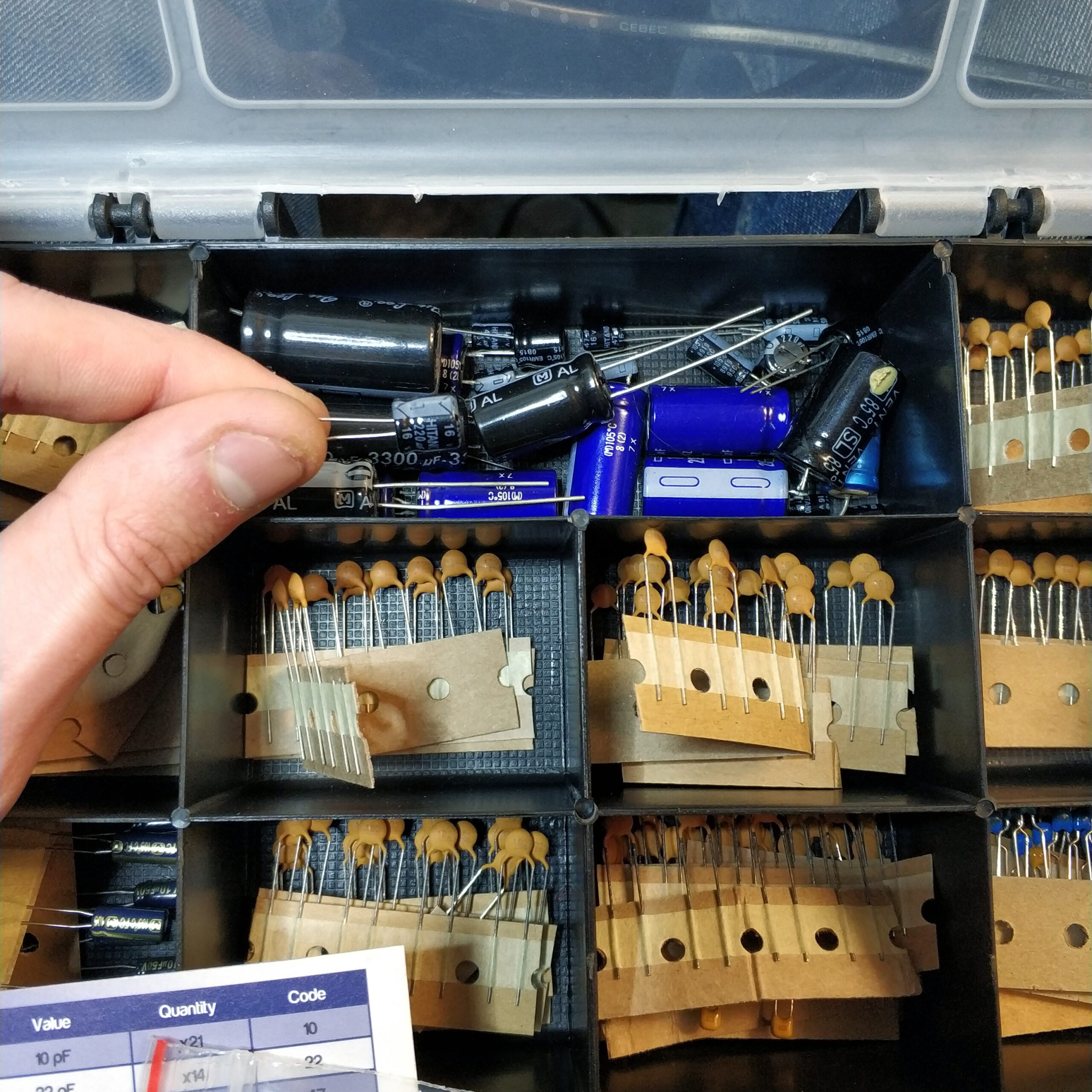
Neben zwölf weißen LEDs brauchte ich noch vier Dioden, einen Elektrolytkondensator und viele Kabel und Schrumpfschlauch.
Als erstes habe ich die Spannung gemessen die an einer der Glühbirnenfassungen anliegt. Das Ergebnis waren 12V vermeintliche Gleichspannung. Dieser Fehler wird später noch mal wichtig.
„12 ist nebenbei meine Lieblingszahl da sie die kleinste Natürliche Zahl ist, die man durch 2, 3, 4, 6 und sich selbst Teilen kann. Diese Vielzahl der Teilungsmöglichkeiten ist praktisch überall von nutzen sei es in der Elektronik, Mathematik, Layout, Aufteilen von Dingen zwischen Personen. Nicht ohne Grund hat man das Jahr in 12 Monate geteilt oder das den Tag in zwei mal 12 Stunden. Ode an die 12.“
Die weißen LEDs brachen ca. 3V Spannung genau weiß ich das nicht aber das ist in diesem Fall nicht so wichtig. Was man sich immer gut merken kann ist das rote LEDs ca 1,5V benötigen und je weiter man im Farbspektrum Richtung kurzwelliger Farben wie blau geht desto mehr Spannung benötigt man. Blaue LEDs liegen so ca. bei 3-4V. Da weißes LED-Licht entweder aus der Mischung von rotem, gelbem, und blauem Licht erzeugt wird oder aus blauem Licht mit einem lumineszierendem Material, dass das Farbspektrum in den monochromatischen Farbraum verschiebt, kann man für weiße LEDs auch eine Spannung von 3-4V annehmen.
Für diesen Anwendungsfall wäre eine Annahme von 3V bei 12V Spannung fast ideal da man so einfach vier LEDs in Reihe schalten könnte und so seine 12V Spannungsabfall bekommen würde. 4 x 3V = 12V (s. mittleren Teil der Grafik)
Dann könnte man das ganze drei mal parallel machen und würde so zwölf leuchtende LEDs erhalten. (s. unteren teil der Grafik)
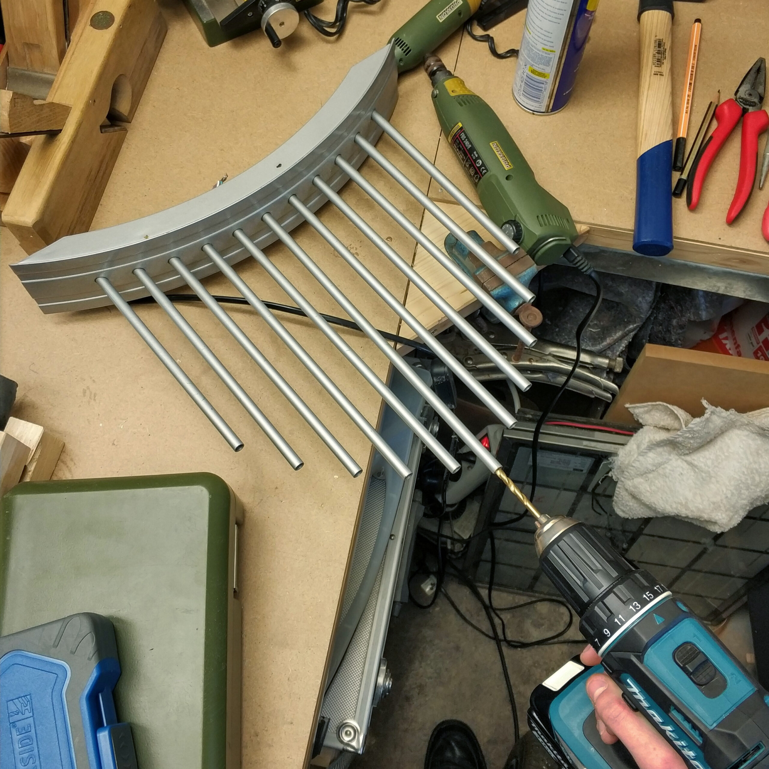
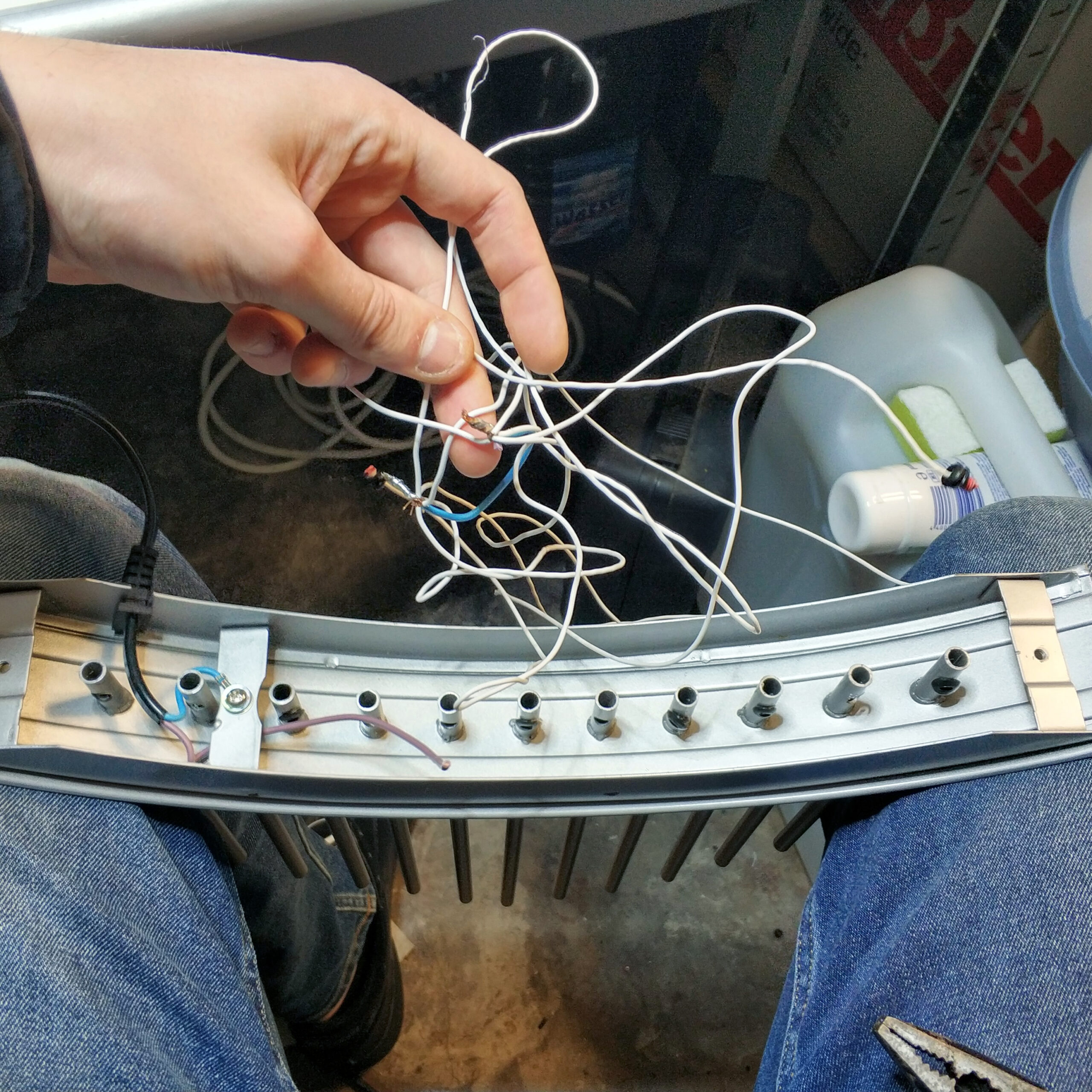
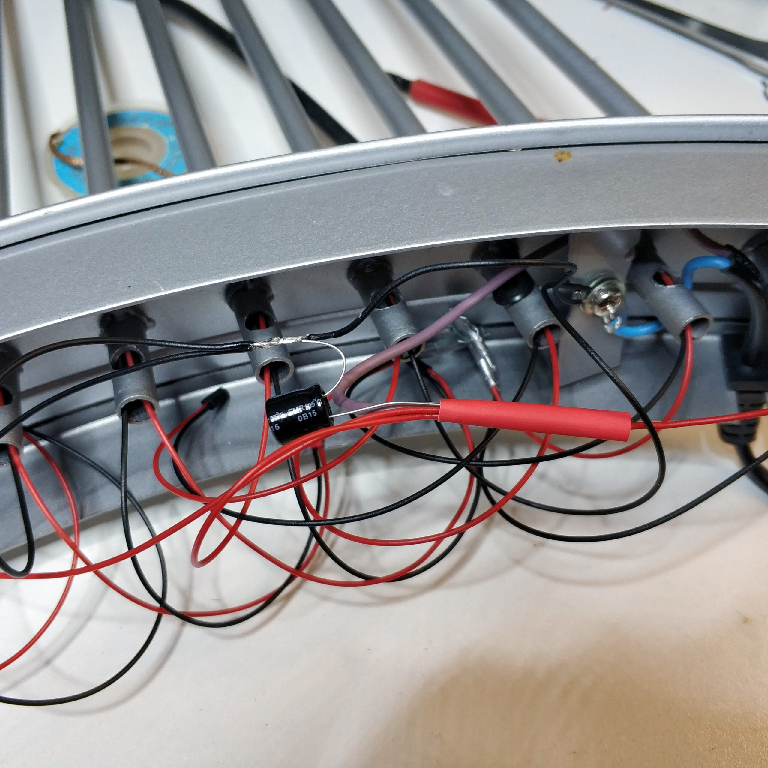
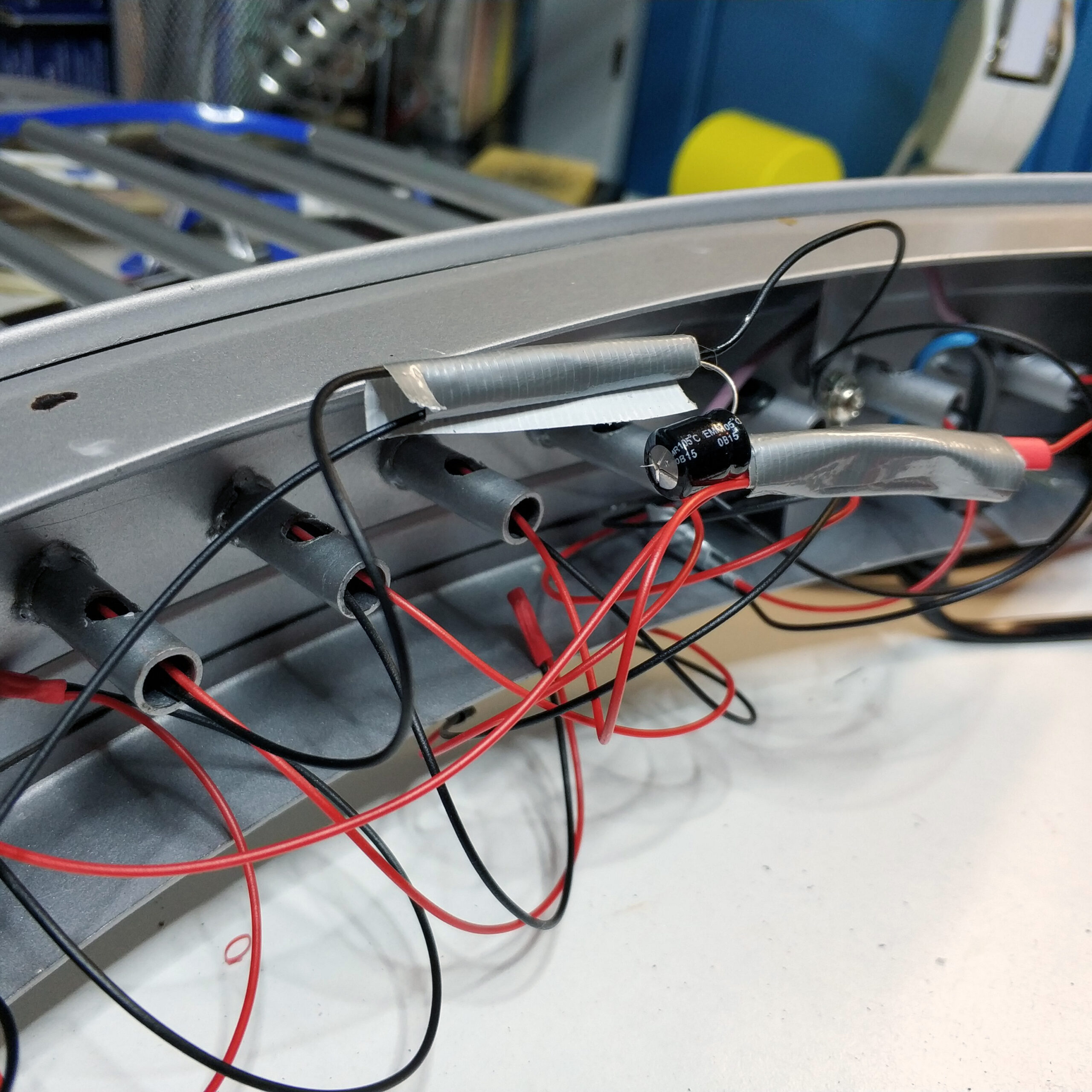
Dummerweise hat der Schwibbogen nur 11 Zinken. Das heißt man müsste in einer Reihenschaltung eine LED weniger einbauen mit der Gefahr das dann die drei LEDs in Reihe 4V statt 3V bekommen was diese zerstören könnte oder faul sein und eine LED im Gehäuse verstecken. Ich habe beides Probiert und bei ersterem zwei LEDs links und rechts von der Mitte kaputt gemacht (s. Bilder) und mich dann für die faule Variante entschieden.
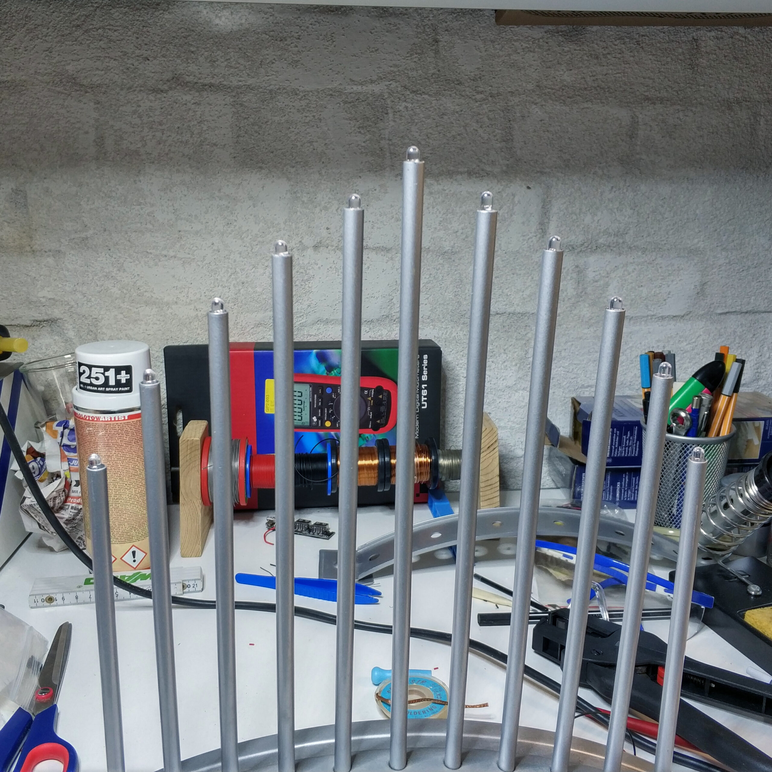
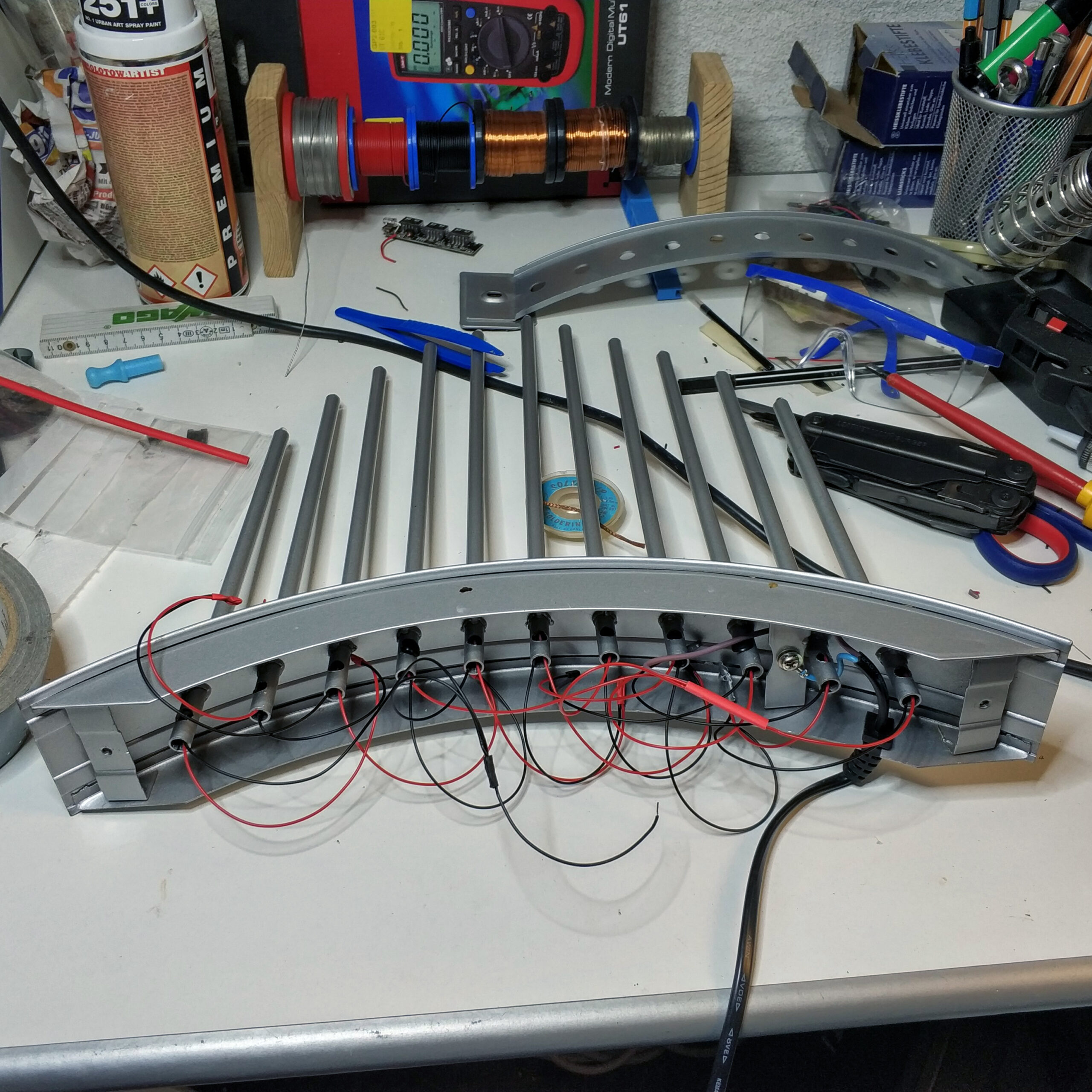
Bei der Umsetzung musste ich als aller erstes die alten Glühbirnenfassungen mit einem Bohrer entfernen. Von unten habe ich dann alle alten Kabel herausgezogen, da das Metall des Schwibbogen selbst als ein Leiter fungiert hat. Also alle Glühbirnen würden parallel geschaltet über je ein Kabel und das Metall. Da ich aber die LEDs in Reihe und Parallel schalten muss waren die alten Kabel unbrauchbar.
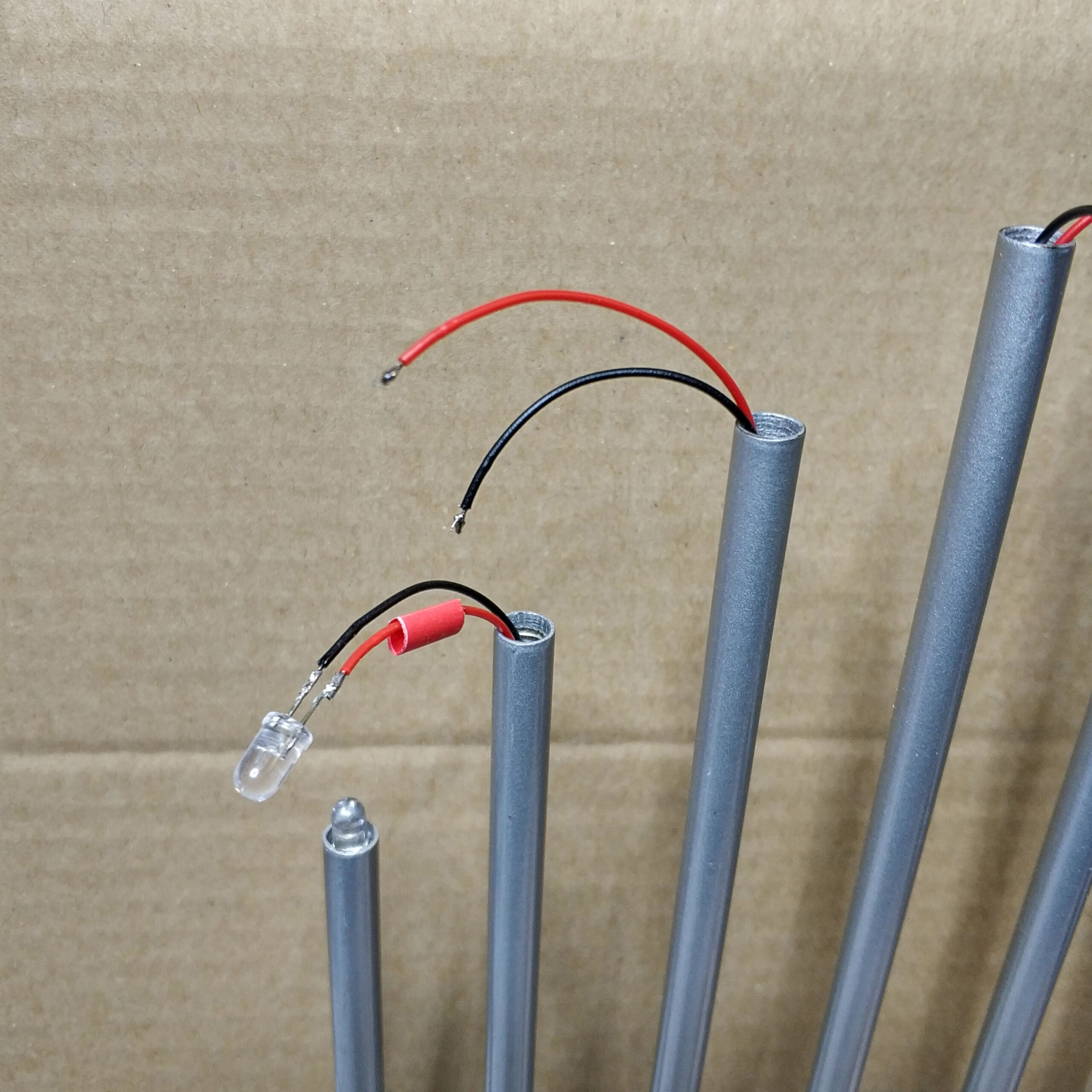
Nach dem entfernen der Innereinen habe ich angefangen Kabel durch die Zinken zu ziehen und and die Enden der Kabel die LEDs zu löten. Glücklicherweise haben die Reste der Glühbirnenfassungen die LEDs am durchrutschen gehindert und weiteres verkleben war nicht mehr nötig.
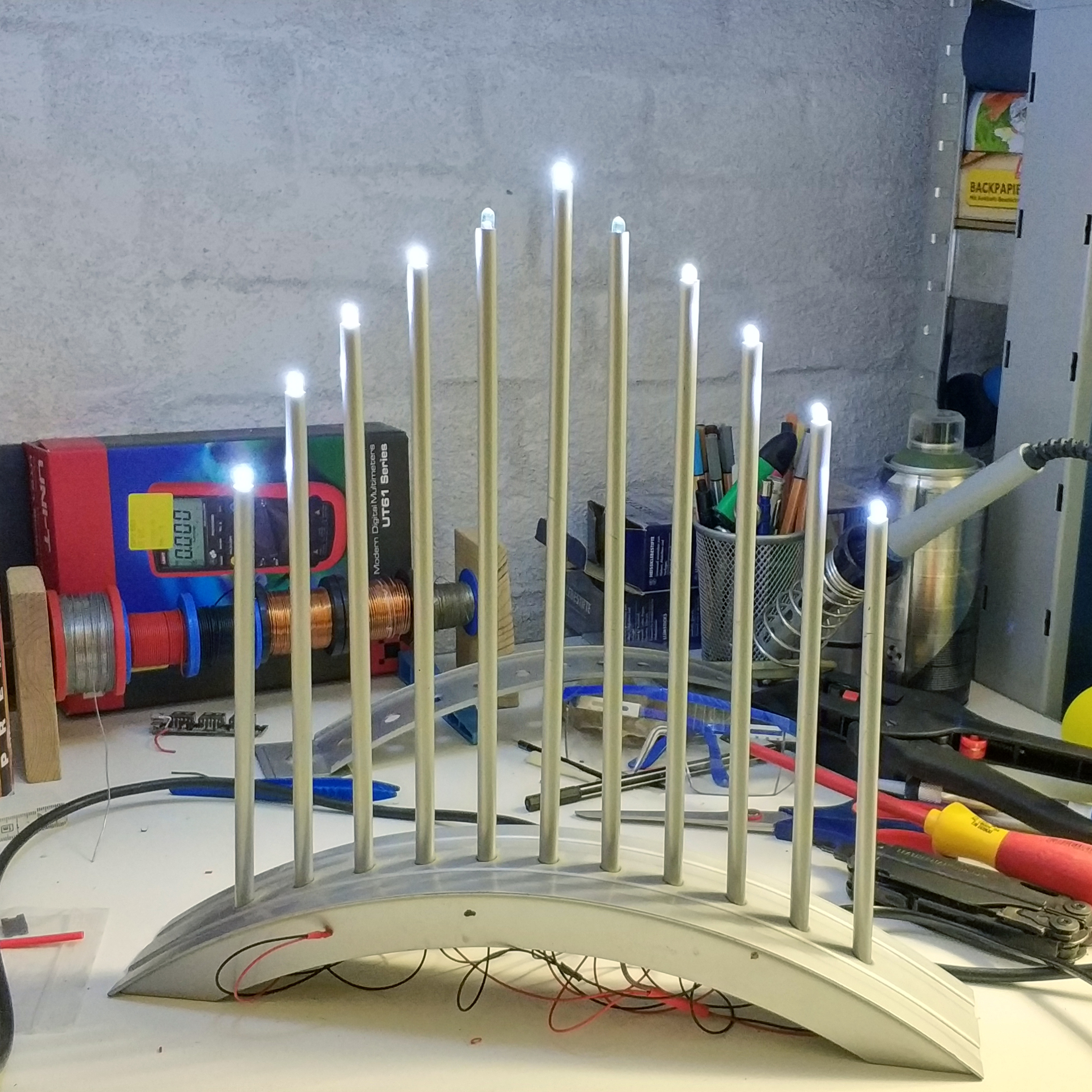
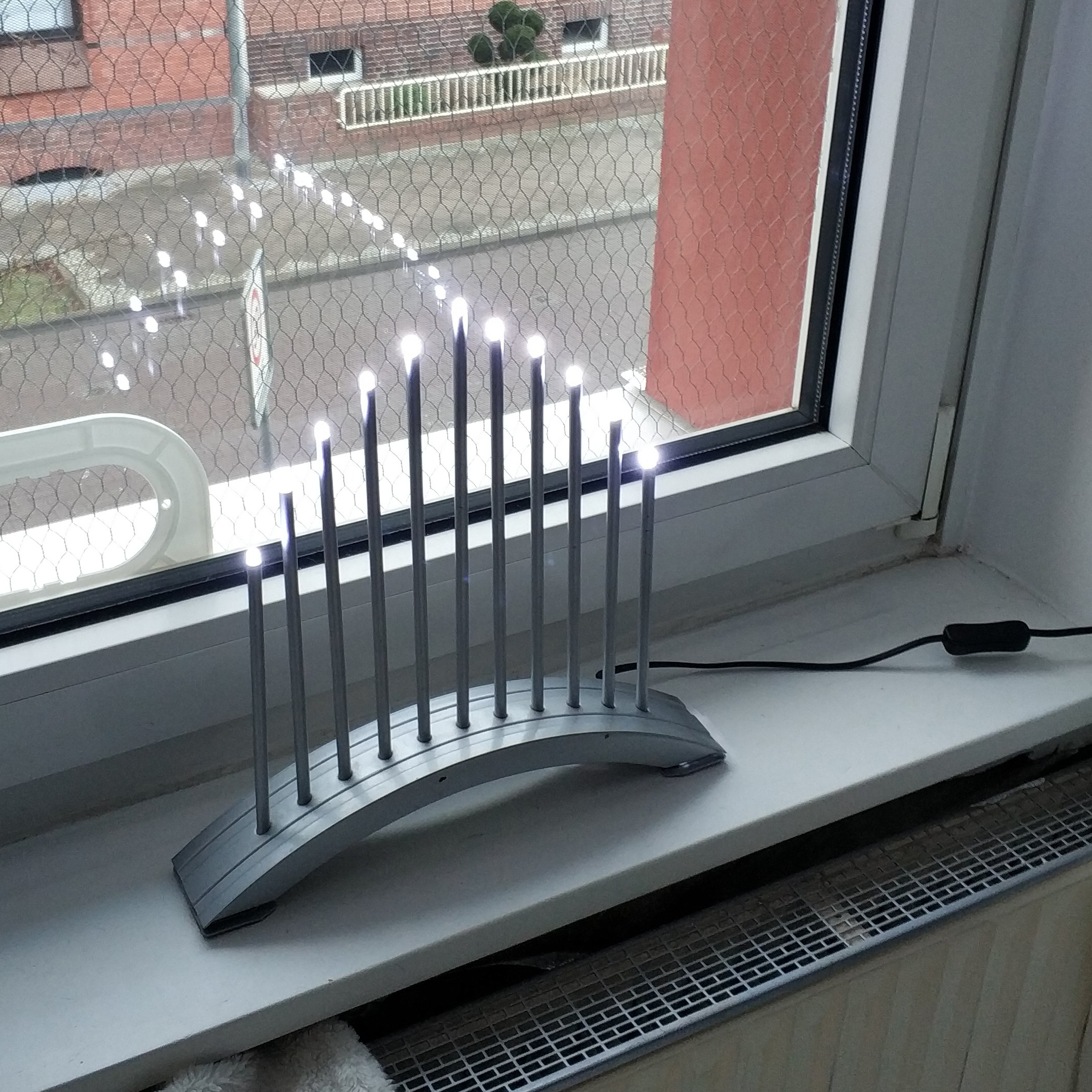
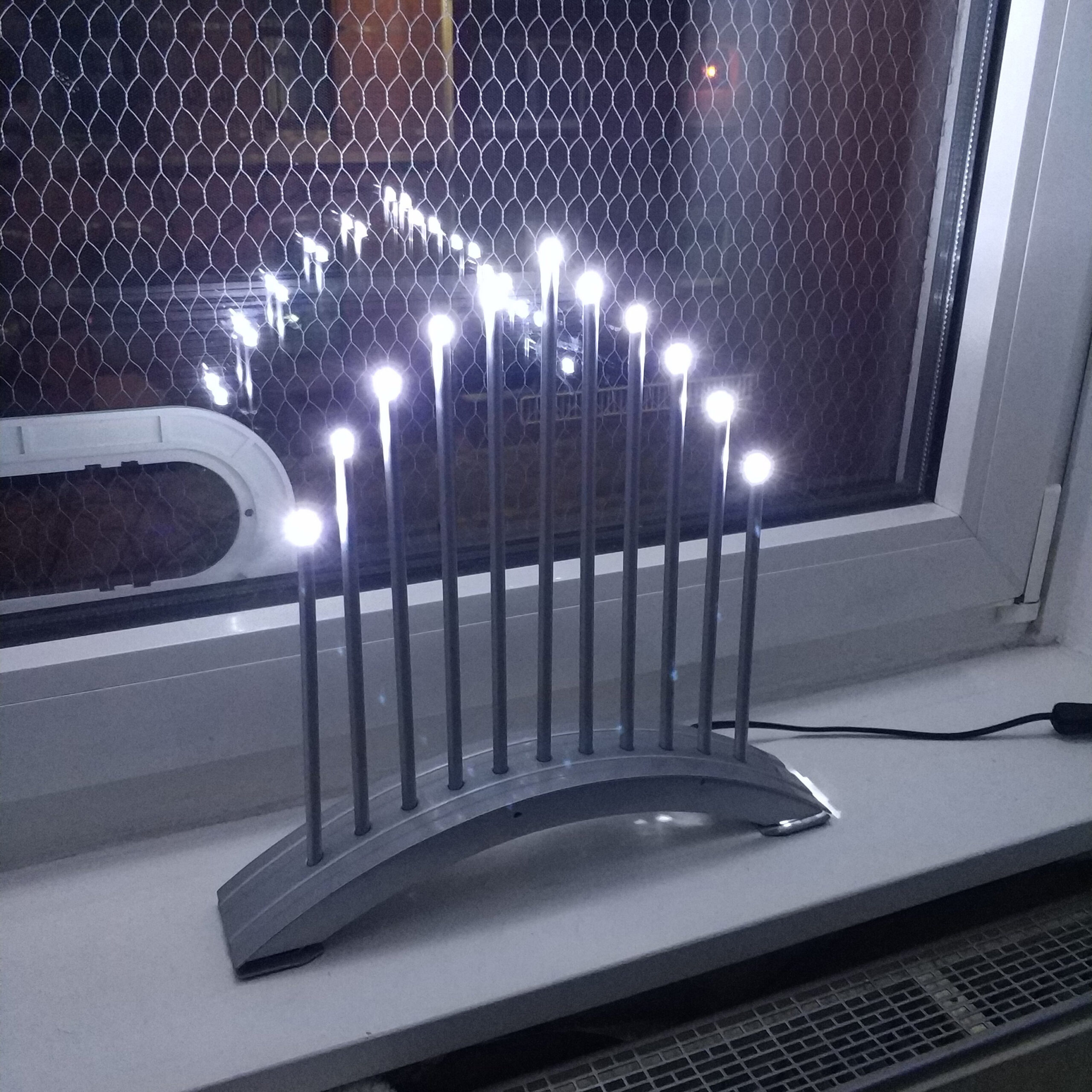
Nach dem ersten Testen haben fast alle LEDs gleich hell geleuchtet bis auf die jenen 3 in der Mitte. Die LEDs links und rechts von der Mitte waren dunkler und waren später ganz kaputt. Ich vermute die erwähnten 4V haben ihnen nicht gut getan. Warum die mittlere unberührt geblieben ist weiß ich auch nicht genau.
Weiterhin haben alle LEDs geflackert, was logischerweise auf dem Bild nicht zu sehen war. Hier kommt jetzt der Annahmefehler zum tragen. Ich ging nämlich davon aus dass der Transformator, der die 230V auf 12V transformiert, auch einen Gleichrichter eingebaut hat. Auch weil heute praktisch alle Kleingeräte über Schaltnetzteile mit Gleichstrom versorgt werden, kam ich gar nicht auf die Idee dass das Netzteil nur ein Transformator ist.
Ich ging davon aus dass das Flackern durch die kurzen Spannungsabfälle durch den Gleichrichter hervorgerufen wurden. (s. grüne kurve mittleres Spannungskurve Diagramm) Daher dachte ich das man das Problem mit einem Kondensator zwischen dem Plus- und Minuspol beheben könnte. Das hat es auch tatsächlich für ca. 5 Sekunden bis der Elektrolytkondensator explodiert ist.
Elektrotechnik Grundkurs:
Das falscheherum Anschließen eines Elektrolytkondensator an eine Gleichstromquell und im Gleichen Sinne auch an eine Wechselspannung ist ein Todesurteil für diese Art Kondensatoren.
Nach dieser Elektrotechnik-Auffrischungs-Erfahrung ist mir dann auch klar geworden das an den Kabelausgängen 12V Wechselspannung anliegt. Nach dem Bau des Gleichrichter und erneuter Verkabelung hatte ich einen leuchtenden Schwibbogen.
Im Folgenden möchte ich daher noch mal näher auf das Thema mit Hilfe der Grafik eingehen…
An almost ancient Schwibbogen, from Ikea, from the era of lightbulbs has needed to be converted to LEDs for years because one bulb after the other has given up the ghost and replacements are no longer available.
The beginning of the Christmas season gave me the impulse not to let another year pass and to implement the project.
In addition to twelve white LEDs, I also needed four diodes, an electrolytic capacitor and lots of cables and shrink tubing.
First I measured the voltage that was applied to one of the light bulb sockets. The result was a supposedly 12V DC voltage. This mistake will be important again later.
„12 is by the way my favorite number because it is the smallest natural number that you can divide by 2, 3, 4, 6 and yourself. This multitude of division possibilities can be used practically everywhere, be it in electronics, mathematics, layout, dividing of things between people. It is not without reason that the year has been divided into 12 months or the day into two times 12 hours. Ode to the 12. „
The white LEDs broke about 3V voltage exactly, I don’t know but that is not so important in this case. What you can always remember is that red LEDs need about 1.5V and the further you go in the color spectrum towards short-wave colors like blue, the more voltage you need. Blue LEDs are around 3-4V. Since white LED light is generated either from a mixture of red, yellow and blue light or from blue light with a luminescent material that shifts the color spectrum into the monochromatic color space, a voltage of 3-4V can also be assumed for white LEDs .
For this application, an assumption of 3V at 12V would be almost ideal because you could simply connect four LEDs in series and thus get your 12V voltage drop. 4 x 3V = 12V (see middle part of the graphic)
Then you could do the whole thing three times in parallel and get twelve glowing LEDs. (see lower part of the graphic)
Unfortunately the Schwibbogen only has 11 prongs. That means you would have to install one less LED in a series circuit with the risk that the three LEDs in series would get 4V instead of 3V, which could destroy them or be lazy and hide an LED in the housing. I tried both and broke two LEDs on the first left and right of the middle (see pictures) and then decided on the lazy variant.
During the implementation, the first thing I had to do was remove the old light bulb sockets with a drill. From below I then pulled out all the old cables, as the metal of the Schwibbogen itself acted as a conductor. So all light bulbs would be connected in parallel via a cable and the metal. But since I have to connect the LEDs in series and in parallel, the old cables were unusable.
After removing the inside I started pulling cables through the prongs and soldering the LEDs to the ends of the cables. Fortunately, the remains of the lightbulb sockets prevented the LEDs from slipping through and no further gluing was necessary.
After the first test, almost all LEDs shone equally brightly except for the 3 in the middle. The LEDs to the left and right of the center were darker and later were completely broken. I suspect the 4V mentioned above didn’t do them any good. I don’t know exactly why the middle one remained untouched.
Furthermore, all LEDs flickered, which logically could not be seen in the picture. This is where the acceptance error comes into play. I assumed that the transformer that transforms the 230V to 12V also has a rectifier built in. Also because today practically all small devices are supplied with direct current via switched-mode power supplies, it never occurred to me that the power supply is just a transformer.
I assumed that the flickering was caused by the short voltage drops caused by the rectifier. (see green curve middle voltage curve diagram) Therefore I thought that the problem with a capacitor between the positive and negative pole could be fixed. It actually has this for about 5 seconds until the electrolytic capacitor explodes.
Electrical engineering basic course:
The wrong way of connecting an electrolytic capacitor to a direct current source and in the same sense to an alternating voltage is a death sentence for this type of capacitor.
After this electrical engineering refresher experience, it became clear to me that there is 12V AC voltage at the cable outputs. After building the rectifier and rewiring, I had a glowing candle arch.
In the following I would like to go into more detail on the topic with the help of the graphic …
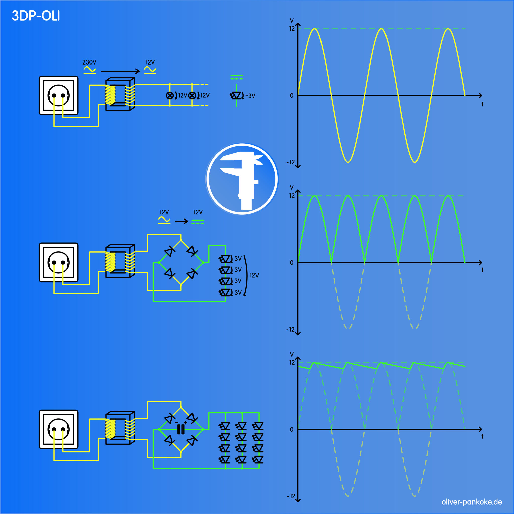
– Die gelben Linien zeigen Teile der Schaltung in den Wechselspannung anliegt.
– Die grünen Linien zeigen Teile der Schaltung in den Gleichspannung anliegt.
– Rechts sieht man die Spannungskurven.
Das obere Schaltbild zeigt die Ausgangsschaltung, in der die elf Glühbirnen parallel and die 12V Wechselspannung angeschlossen sind. Daneben sieht man das Schaltzeichen einer LED und das diese 3V Gleichspannung benötigt. Auf der rechten Seite sieht man in gelb den Spannungsverlauf der Wechselspannung. Die grüne gestrichelte Line zeigt wo wir hin wollen. Mit dem hinzufügen von Komponenten in der Mitte und ganz unten können wir sehen wie wir uns der grünen gestrichelten Line annähren. Links aus der Steckdose kommen 230V Wechselspannung. Diese wird im daneben gezeigten Transformator auf 12V Wechselspannung herunter transformiert. (s. Transformator)
In der Mitte wurde ein Gleichrichter hinzugefügt. Dieser bewirkt das die gelb gestrichelten kurven in den positiven Bereich gebracht werden. Also die Wechselspannung in Gleichspannung umgewandelt wird. Ein Gleichrichter kann leicht selbstgebaut werden aus vier Dioden die die passenden Parameter haben oder auch als fertiges Bauelement gekauft werden. (s. Dioden und Gleichrichter) Daneben ist zusehen wie über die vier LEDs je 3V Spannung abfallen was zusammen die 12V ergibt die aus dem Gleichrichter kommen.
Unten wurde ein Elektrolytkondensator hinzugefügt, um wie rechts zu sehen die kurzzeitigen Spannungsabfälle abzufangen. Wir sind damit jetzt recht nah an der grün gestrichelten Idealline. Da die Netzfrequenz 50Hz ist und diese auch nach dem Gleichrichten präsent ist sollte man eben jenen Kondensator hinzufügen. Da die Frequenz schon recht schnell ist reicht ein Kondensator mit wenigen 100μF um die Abfälle abzufangen. Wäre die Frequenz großer müsste auch die Kapazität größer sein, da die „Spannungslöcher“ breiter werden würden. Wichtig beim Elektrolytkondensator ist es auch auf die Polarität zu achten, sonst hat man nicht lange Freude an der Sache. Weiterhin wurden zwei weitere Reihen von je vier LEDs hinzugefügt um die Gesamtzahl zu erhöhen.
Dabei sind die beiden Schaltkreise wie optisch auch dargestellt nicht direkt elektrisch miteinander verbunden sondern nur über einen Eisenkern. Dieser dient dazu das erzeugte elektromagnetische Feld der ersten Spule in die zweite Spule zu leiten. Durch das Verhältnis der Windungen um den Eisenkern lässt sich die Spannung entsprechend runter- oder auch heraufregeln. In diesem Fall muss die Windungszahl auf der Seite der Steckdose im Idealfall 26,6 mal größer sein als auf der Seite der Glühbirnen. Die Voltzahlen der einen zur anderen Seite sind dabei äquivalent zu der Windungszahl oder ein vielfaches davon.
320V/12V <=> 320n/12n
V = Volt, n = Windungen
Beispielsweise würden 960 Windungen zu 36 Windungen die selbe Spannungstransformation bewirken.
Bitte keinen Transformator selber bauen oder einen bestehenden Aufmachen! Lebensgefahr!
Transformatoren funktionieren nur mit Wechselspannung da nur über ein veränderliches Magnetfeld Spannung über den Eisenkern in die zweite Spule induziert werden kann. Bei Gleichspannung wäre auch ein gleichbleibender Stromfluss, der wiederum ein gleichbleibendes Magnetfeld erzeugt. Die Gegeninduktivität, also der Widerstand, der zweiten Spule würde dem Magnetfeld entgegenwirken und den Stromfluss stoppen. Spulen sind im Gleichstromkreis wie ein einfacher Leiter. Die Drähte im Transformator sind recht dünn und würden daher schnell überhitzen. Im Wechselstromkreis erzeugt das Magnetfeld eine Selbstinduktion die den Strom auch nach Spannungsumkehr weiter fließen lässt und der Spannungsänderung entgegenwirkt wie ein Widerstand. Der Widerstand nimmt aber immer weiter bis der Strom dann in die tatsächlich andere Richtung entsprechend der Spannung fließt. Die Frequenz mit der dies geschieht darf logischerweise nicht zu lang sein bzw. muss auf die Spule und den Leiterquerschnitt abgestimmt sein, da sonst die Fase in der dem Strom kein Widerstand geboten wird zur Überhitzung führen kann.
Dioden lassen Spannung nur in eine Richtung durch und sperren in die andere Richtung (sofern die Spannung nicht zu groß wird). Dioden haben verschiedene Spannungsparameter auf die geachtet werden muss. Zum eine die Flussspannung oder auch Schleusenspannung (UF, US) das die Spannung angibt, ab der die Diode in Flussrichtung leitet. Dieser Wert sollte auf jeden fall kleiner sein als die anliegende Wechselspannung da sonst die Diode in beide Richtungen sperrt, was der Sache nicht dienlich ist. Der Wert darf auch recht klein sein da man sonst die unteren Teile der Spannungskurve praktisch abhakt also keine Spannung anliegt. Der Andere wichtige Spannungswert ist die Durchbruchsspannung (UD o. URRM). Diese gibt an, ab wann die Diode entgegen der Flussrichtung nicht mehr sperrt. Dieser Wert muss auch auf jeden Fall größer sein als die eingehende Wechselspannung da der Geleichrichter seine Funktion nicht mehr erfüllt. Der letzte wichtige wert ist die Diffusionsstrom (IF). Dieser gibt an wie viel Strom durch die Diode in Flussrichtung fließen kann. Ist dieser zu klein limitiert das grob gesagt die Leistungsfähigkeit der Verbraucher. Um das in diesem Fall grob einschätzen zu können muss man den Stromfluss aller LEDs addieren. Eine weiße LED benötigt ca. 20-25mA. Das dann mal 12 ergibt ca. 240-300mA. IF sollte also größer sein als 300mA. Wenn IF wesentlich größer ist sollte das der Sache nicht Schaden und ist in diesen niederen Spannungsregionen auch nicht ganz so wichtig. Mehr Gedanken sollte man sich machen je mehr Strom die Verbraucher benötigen und auch je höher die Spannung wird.
Bitte nicht auf die Idee kommen einen 230V Gleichrichter zu bauen und dann an die Steckdose anzuschließen. Mal wieder Lebensgefahr!
– The yellow lines show parts of the circuit in which AC voltage is applied.
– The green lines show parts of the circuit in which DC voltage is applied.
– On the right you can see the voltage curves.
The upper circuit diagram shows the output circuit in which the eleven light bulbs are connected in parallel to the 12V AC voltage. Next to it you can see the circuit symbol of an LED and that this 3V DC voltage is required. On the right side you can see the voltage curve of the alternating voltage in yellow. The green dashed line shows where we want to go. With the addition of components in the middle and at the very bottom, we can see how we approach the green dashed line. 230V AC voltage comes out of the socket on the left. This is transformed down to 12V AC voltage in the transformer shown next to it. (see transformer)
A rectifier was added in the middle. This causes the yellow dashed curves to be brought into the positive area. So the alternating voltage is converted into direct voltage. A rectifier can easily be built by yourself from four diodes that have the appropriate parameters or can be purchased as a finished component. (See diodes and rectifiers) In addition, you can see how the four LEDs each drop 3V voltage, which together results in the 12V that come from the rectifier.
An electrolytic capacitor was added at the bottom to absorb the short-term voltage drops as shown on the right. We are now very close to the green dashed ideal line. Since the mains frequency is 50Hz and this is also present after rectification, you should add that capacitor. Since the frequency is already quite fast, a capacitor with a few 100μF is enough to catch the waste. If the frequency were higher, the capacitance would also have to be higher, since the „voltage holes“ would become wider. It is also important to pay attention to the polarity of the electrolytic capacitor, otherwise you will not be able to enjoy the thing for long. Two more rows of four LEDs each were added to increase the total.
As shown optically, the two circuits are not directly electrically connected to one another but only via an iron core. This serves to guide the electromagnetic field generated by the first coil into the second coil. The voltage can be adjusted down or up accordingly through the ratio of the turns around the iron core. In this case, the number of turns on the socket side should ideally be 26.6 times greater than on the side of the lightbulbs. The voltages from one side to the other are equivalent to the number of turns or a multiple thereof.
320V / 12V <=> 320n / 12n
V = volts, n = turns
For example, 960 turns to 36 turns would cause the same voltage transformation.
Please do not build a transformer yourself or open an existing one! Risk of death!
Transformers only work with alternating voltage because voltage can only be induced into the second coil via the iron core via a variable magnetic field. With direct voltage there would also be a constant flow of current, which in turn generates a constant magnetic field. The mutual inductance, i.e. the resistance, of the second coil would counteract the magnetic field and stop the flow of current. Coils are like a simple conductor in a DC circuit. The wires in the transformer are quite thin and would therefore quickly overheat. In the alternating current circuit, the magnetic field creates a self-induction that allows the current to continue flowing even after the voltage has been reversed and counteracts the change in voltage like a resistor. The resistance increases until the current actually flows in the other direction according to the voltage. The frequency with which this happens must logically not be too long or must be matched to the coil and the conductor cross-section, otherwise the chamfer in which the current is not offered any resistance can lead to overheating.
Diodes only pass voltage through in one direction and block in the other direction (provided the voltage is not too high). Diodes have different voltage parameters that must be taken into account. On the one hand the forward voltage or also the lock voltage (UF, US) which indicates the voltage from which the diode conducts in the forward direction. In any case, this value should be smaller than the applied alternating voltage, otherwise the diode blocks in both directions, which is not useful. The value can also be quite small, otherwise the lower parts of the voltage curve are practically ticked off so there is no voltage. The other important voltage value is the breakdown voltage (UD or URRM). This indicates when the diode no longer blocks against the direction of flow. In any case, this value must be greater than the incoming AC voltage because the rectifier no longer fulfills its function. The last important value is the diffusion current (IF). This indicates how much current can flow through the diode in the forward direction. If this is too small, it roughly limits the performance of the consumer. In order to be able to roughly estimate this in this case, you have to add the current flow of all LEDs. A white LED needs about 20-25mA. That times 12 results in approx. 240-300mA. So IF should be greater than 300mA. If the IF is much larger, it shouldn’t hurt and is not that important in these lower voltage regions. The more electricity the consumers need and the higher the voltage, the more you should think about.
Please do not get the idea to build a 230V rectifier and then connect it to the socket. Danger to life again!