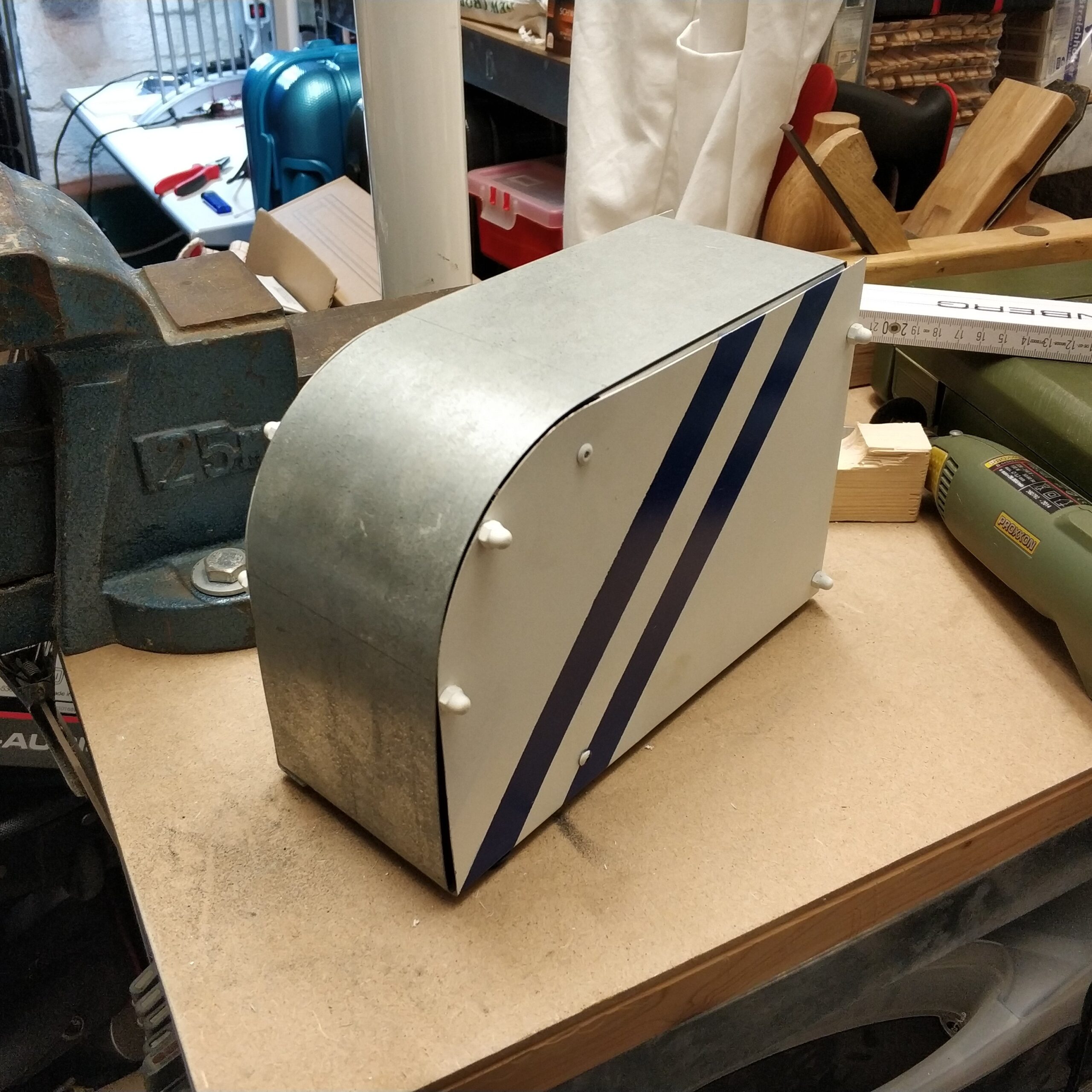
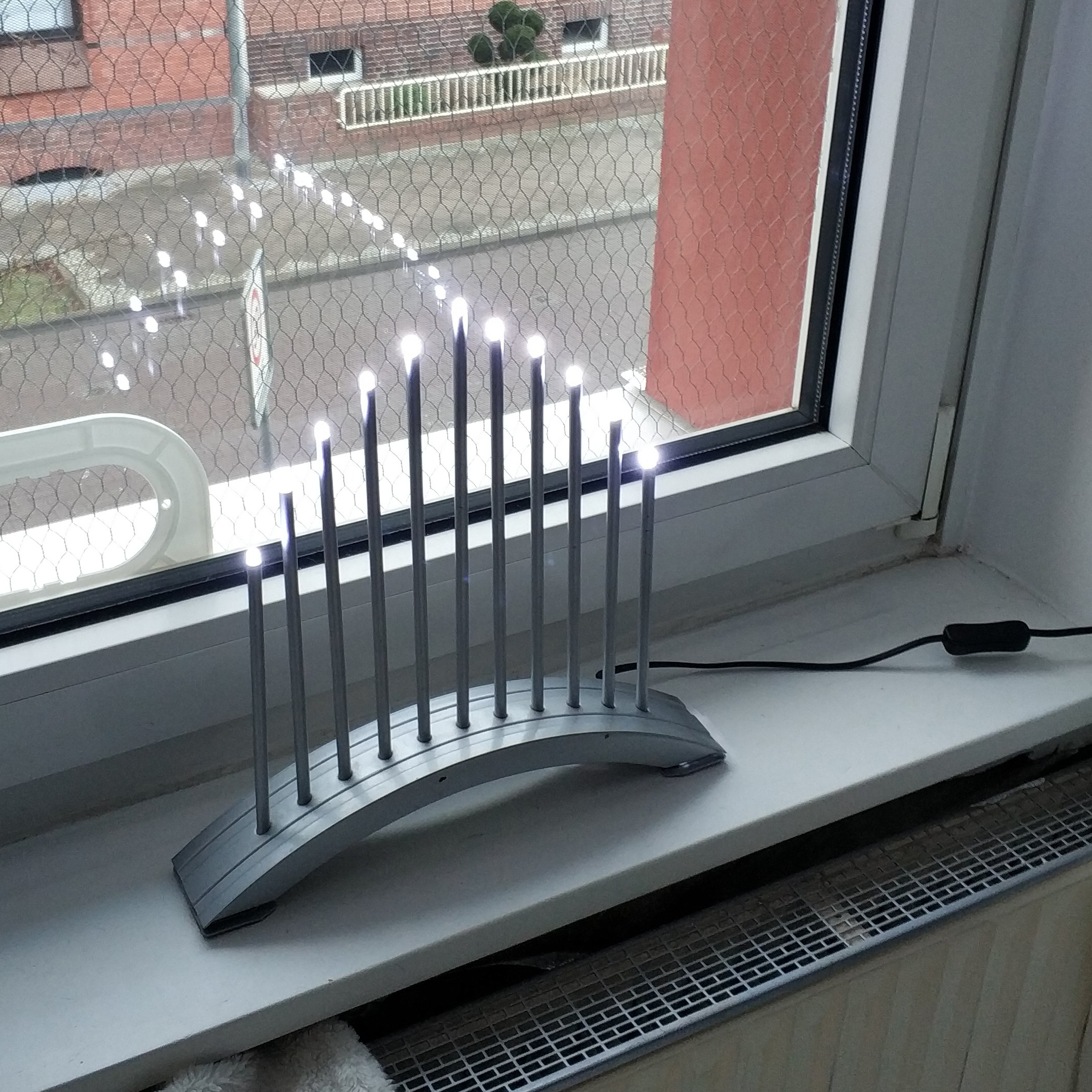
An almost ancient Schwibbogen, from Ikea, from the era of lightbulbs has needed to be converted to LEDs for years because one bulb after the other has given up the ghost and replacements are no longer available.
The beginning of the Christmas season gave me the impulse not to let another year pass and to implement the project.
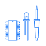
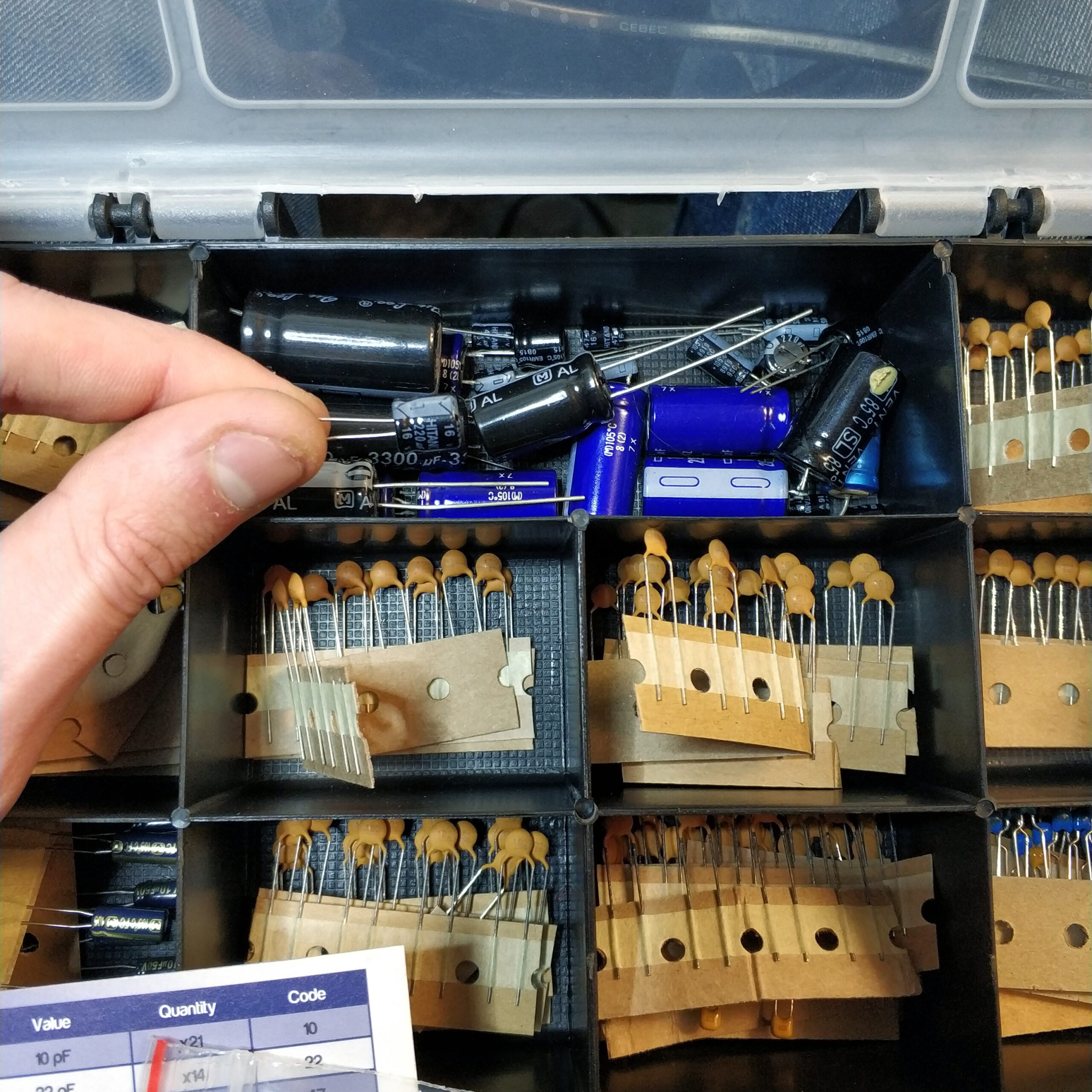
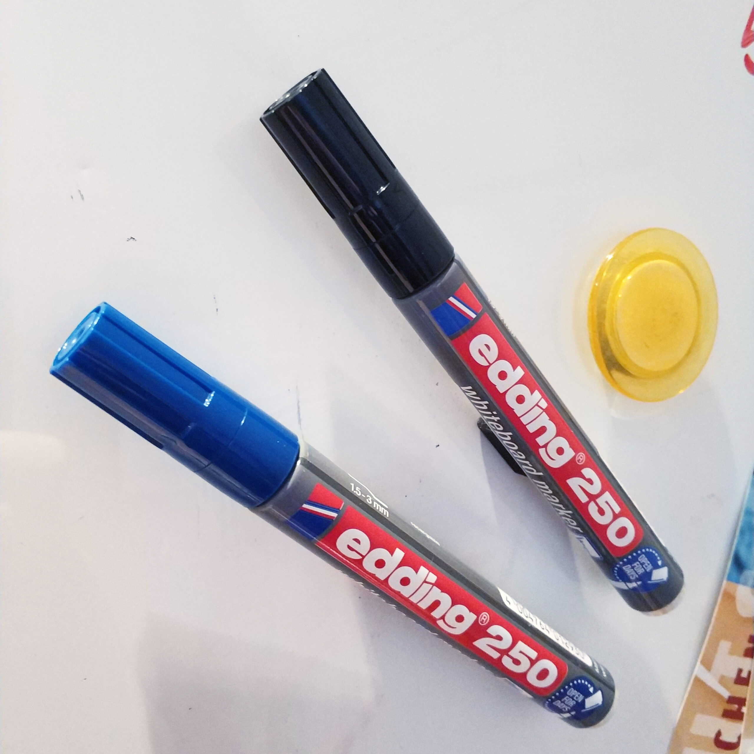
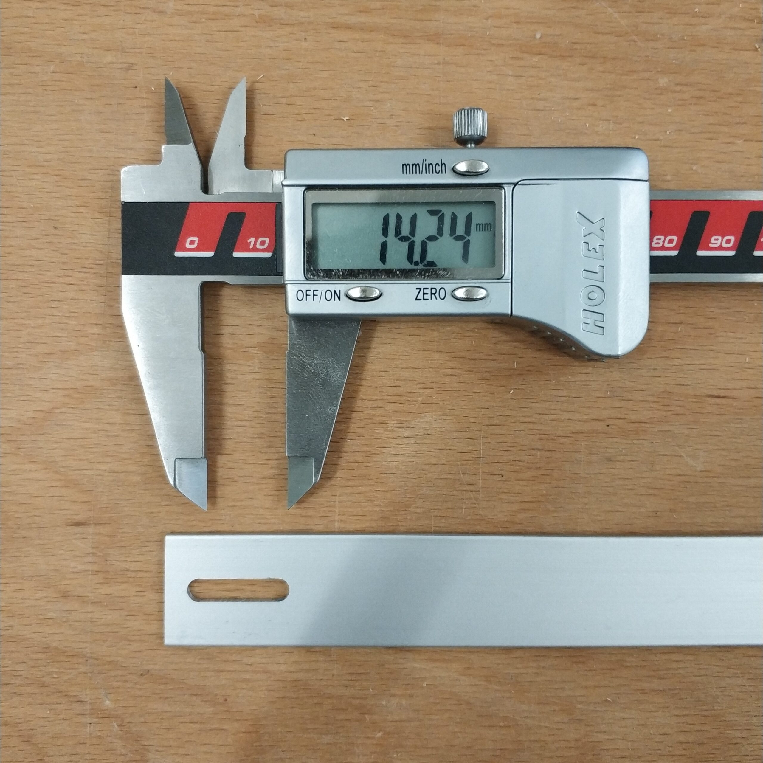
In addition to twelve white LEDs, I also needed four diodes, an electrolytic capacitor and lots of cables and shrink tubing.
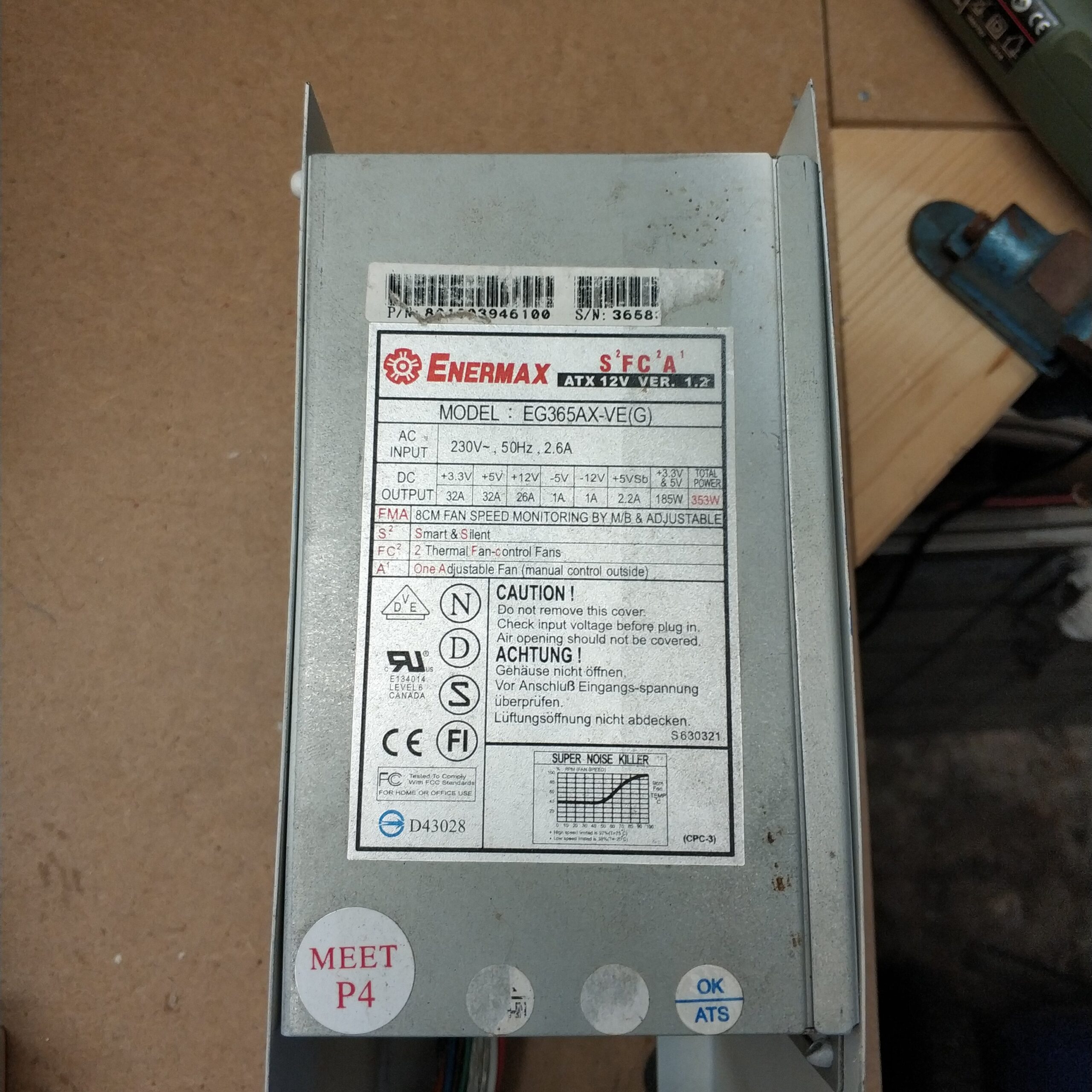
First I measured the voltage that was applied to one of the light bulb sockets. The result was a supposedly 12V DC voltage. This mistake will be important again later.
„12 is by the way my favorite number because it is the smallest natural number that you can divide by 2, 3, 4, 6 and yourself. This multitude of division possibilities can be used practically everywhere, be it in electronics, mathematics, layout, dividing of things between people. It is not without reason that the year has been divided into 12 months or the day into two times 12 hours. Ode to the 12. „
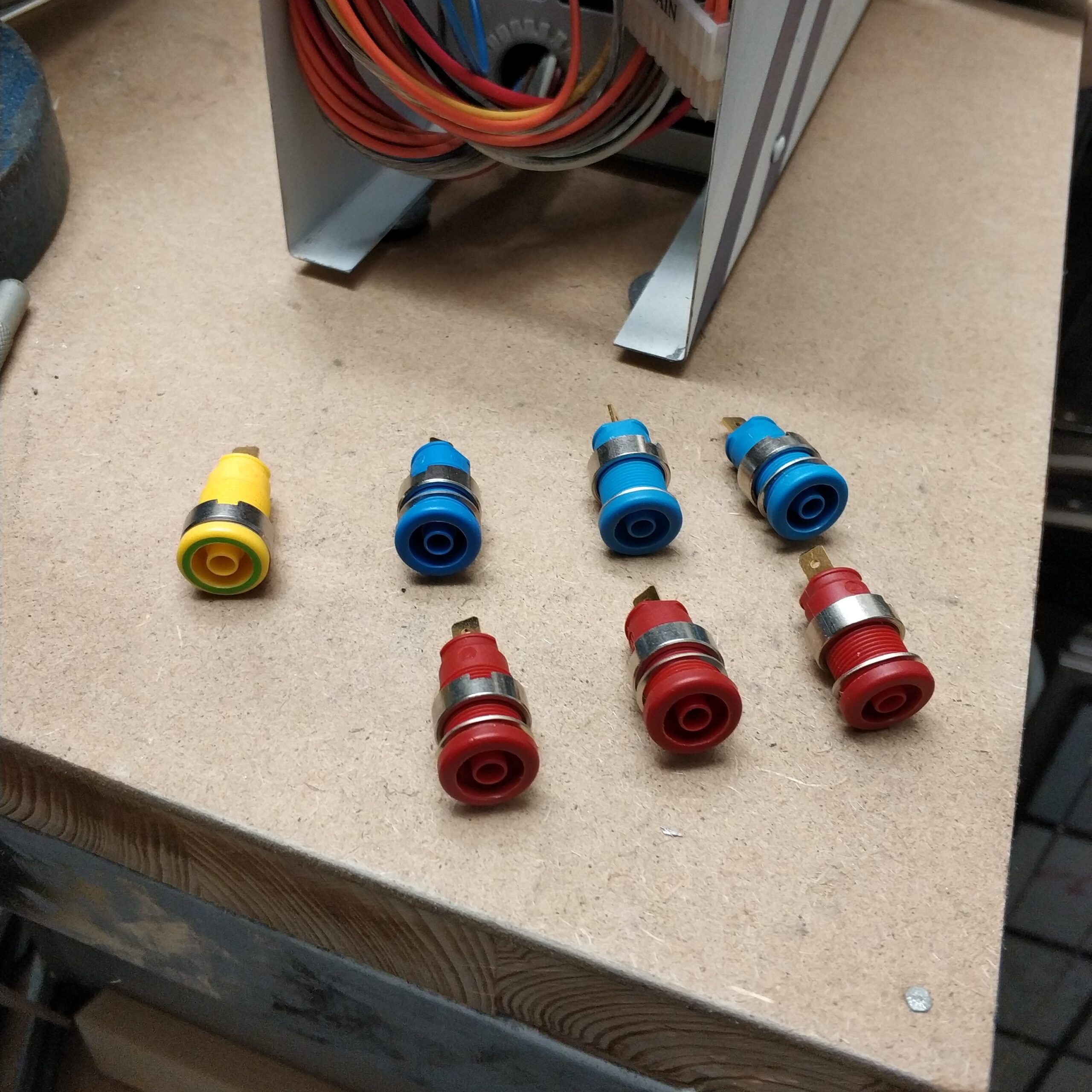
The white LEDs broke about 3V voltage exactly, I don’t know but that is not so important in this case. What you can always remember is that red LEDs need about 1.5V and the further you go in the color spectrum towards short-wave colors like blue, the more voltage you need. Blue LEDs are around 3-4V. Since white LED light is generated either from a mixture of red, yellow and blue light or from blue light with a luminescent material that shifts the color spectrum into the monochromatic color space, a voltage of 3-4V can also be assumed for white LEDs .
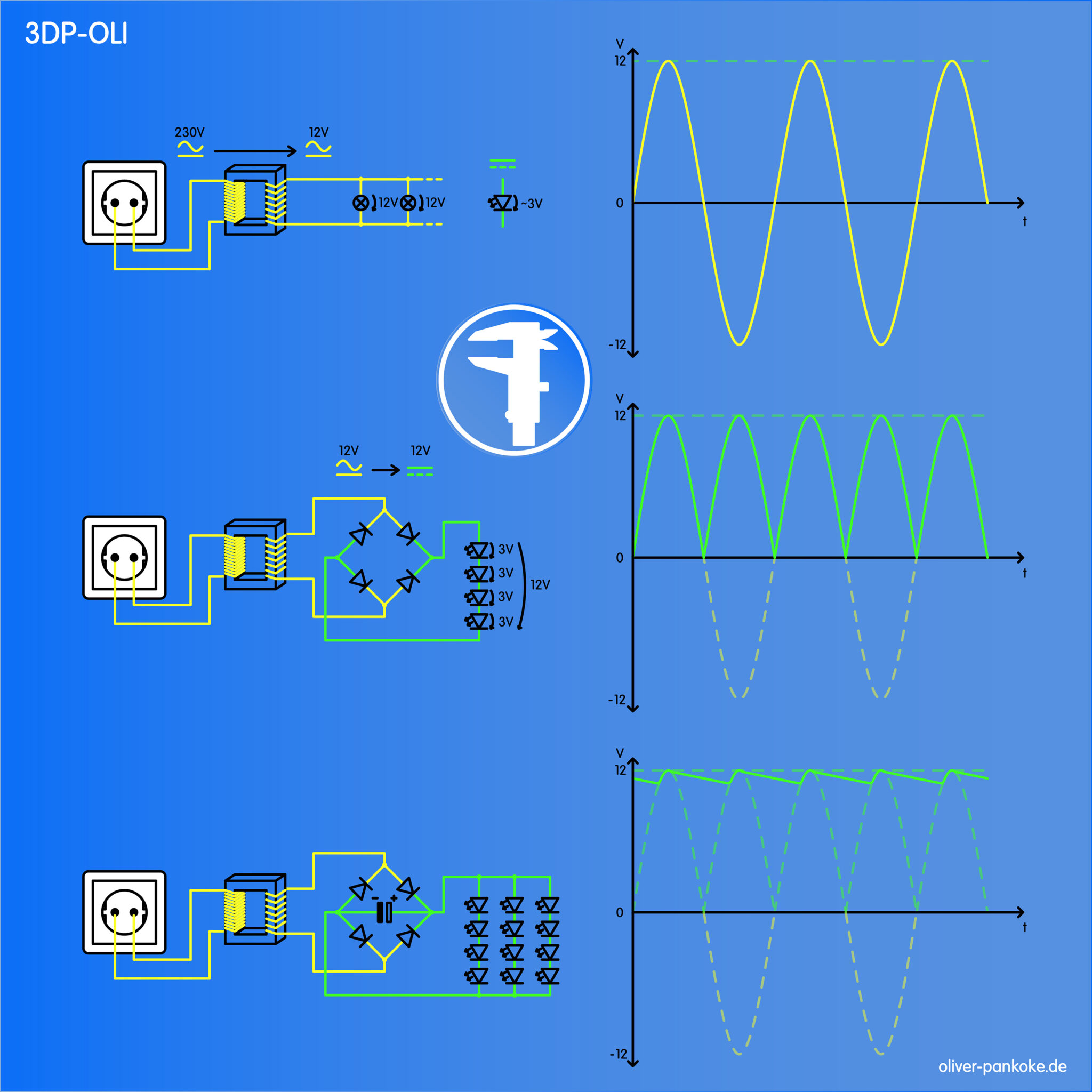
For this application, an assumption of 3V at 12V would be almost ideal because you could simply connect four LEDs in series and thus get your 12V voltage drop. 4 x 3V = 12V (see middle part of the graphic)
Then you could do the whole thing three times in parallel and get twelve glowing LEDs. (see lower part of the graphic)
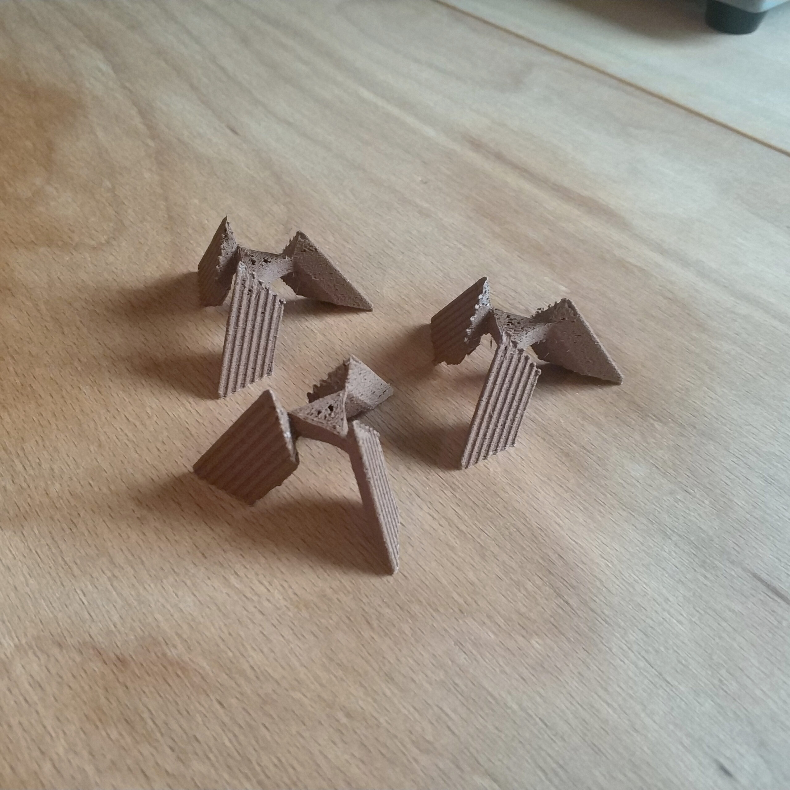
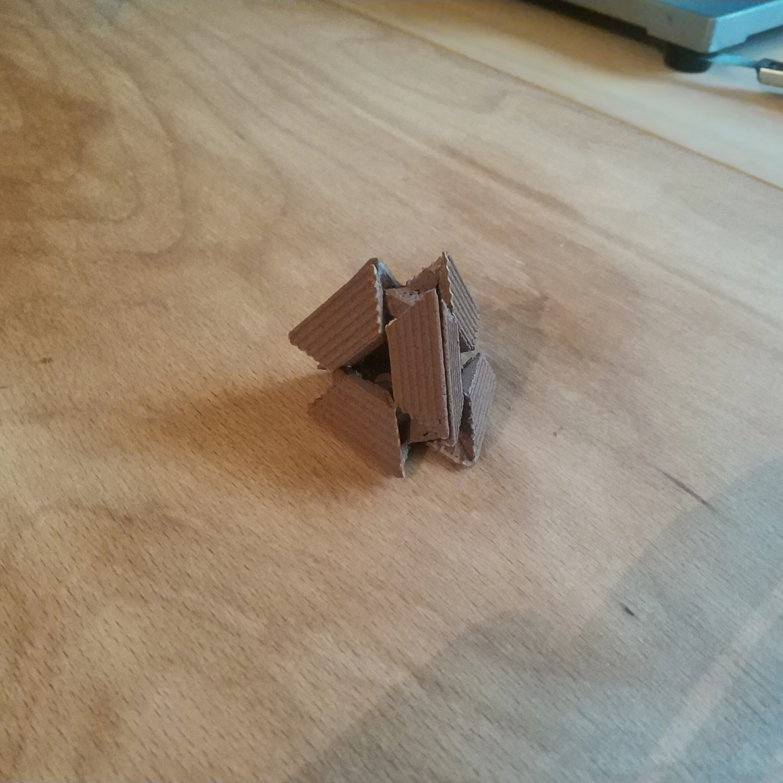
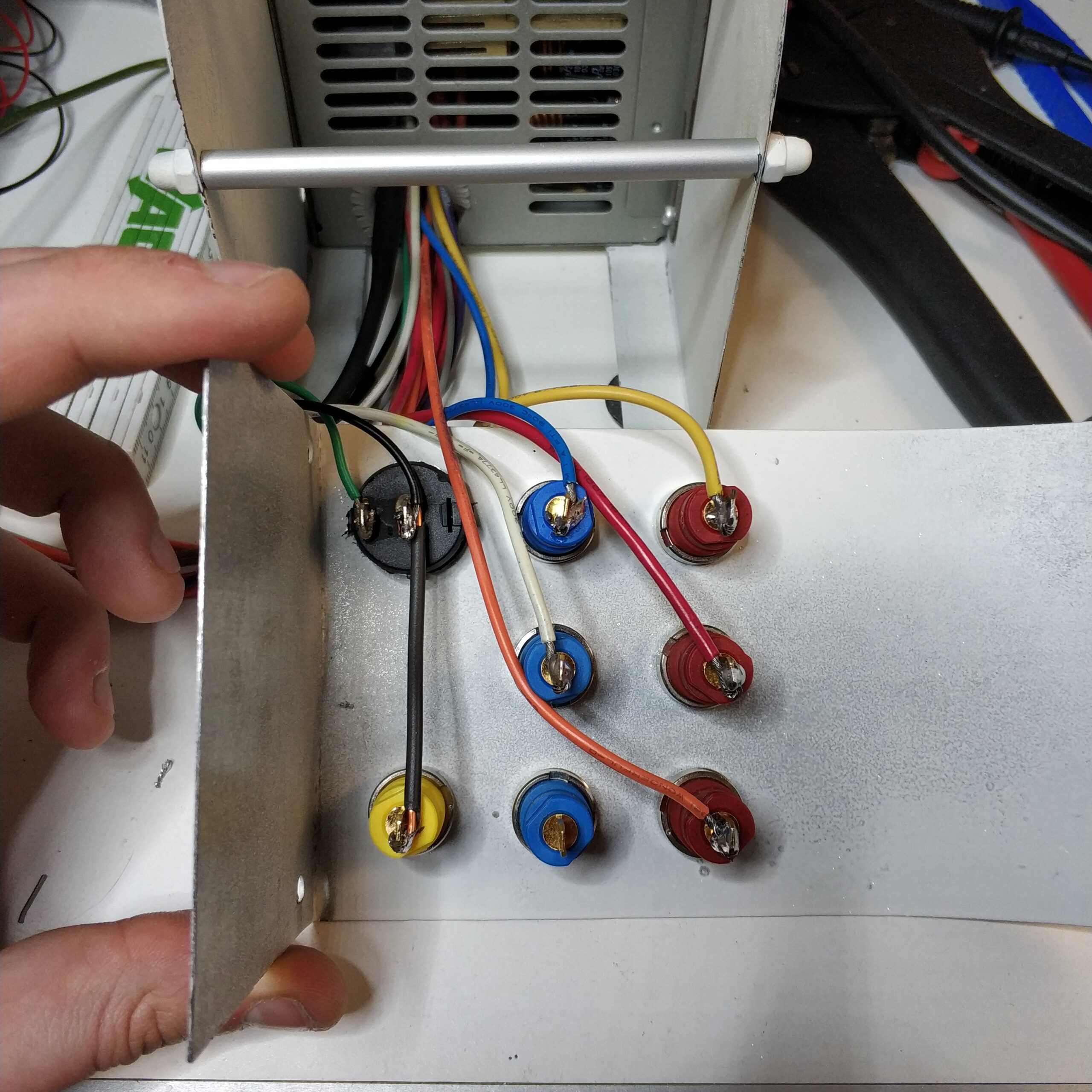
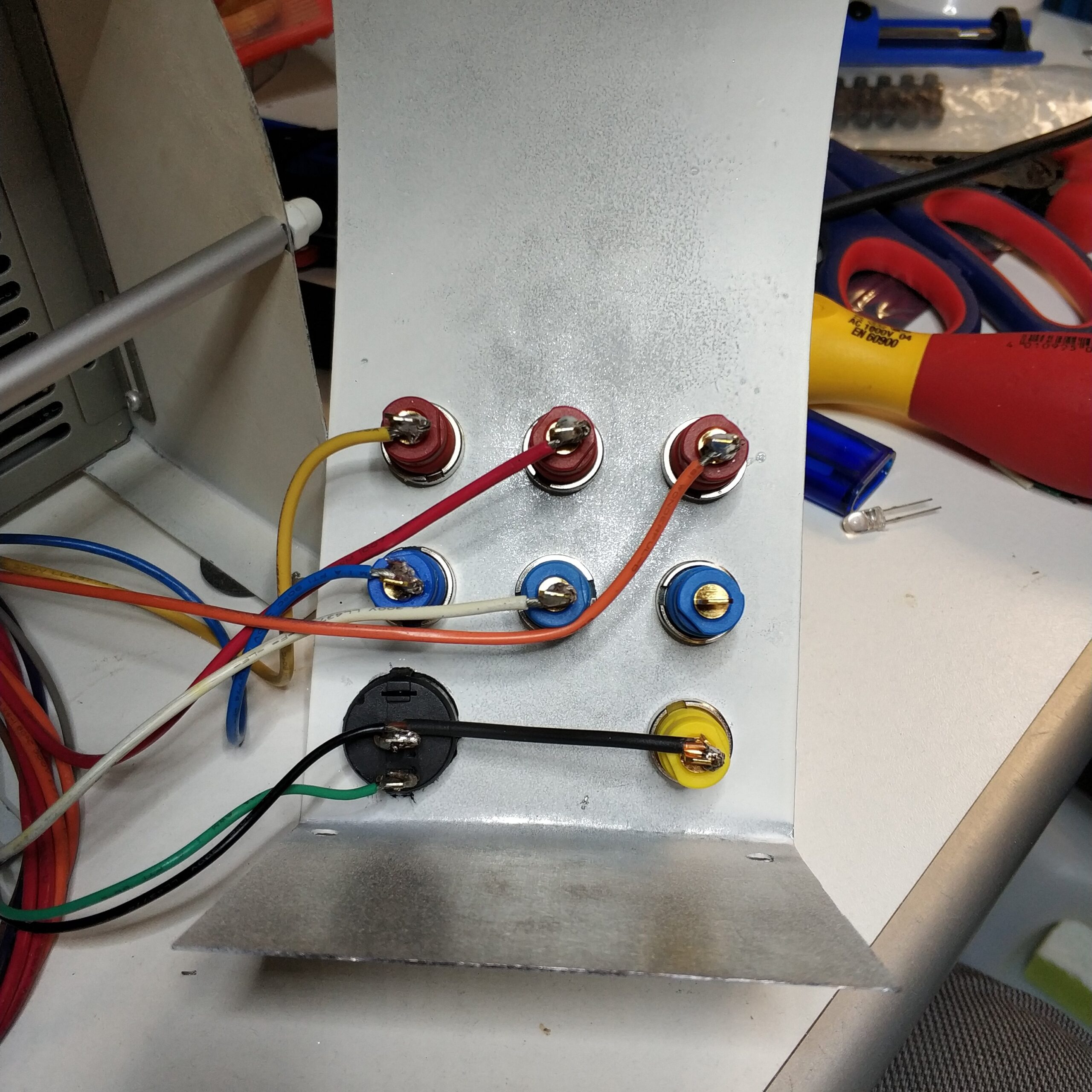
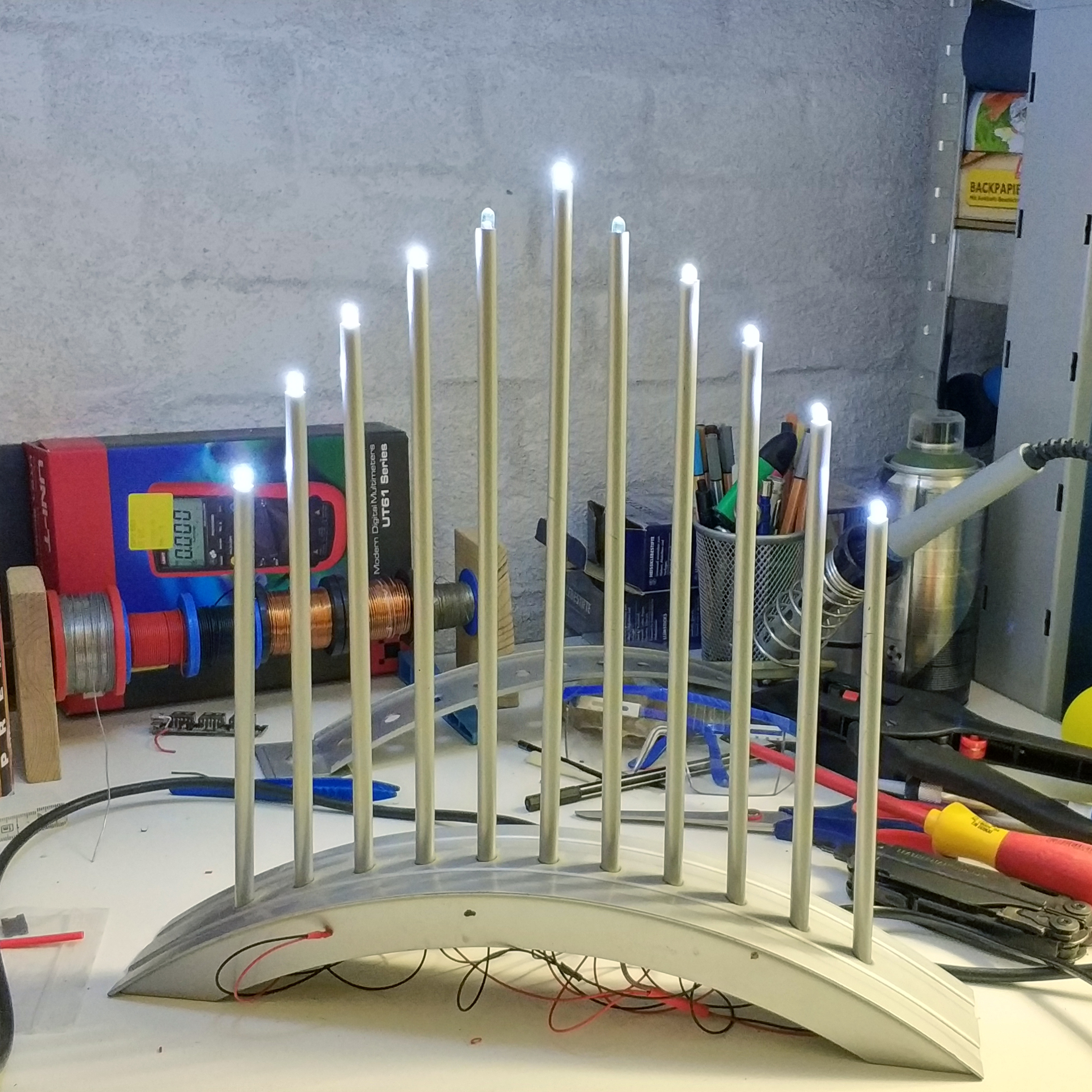
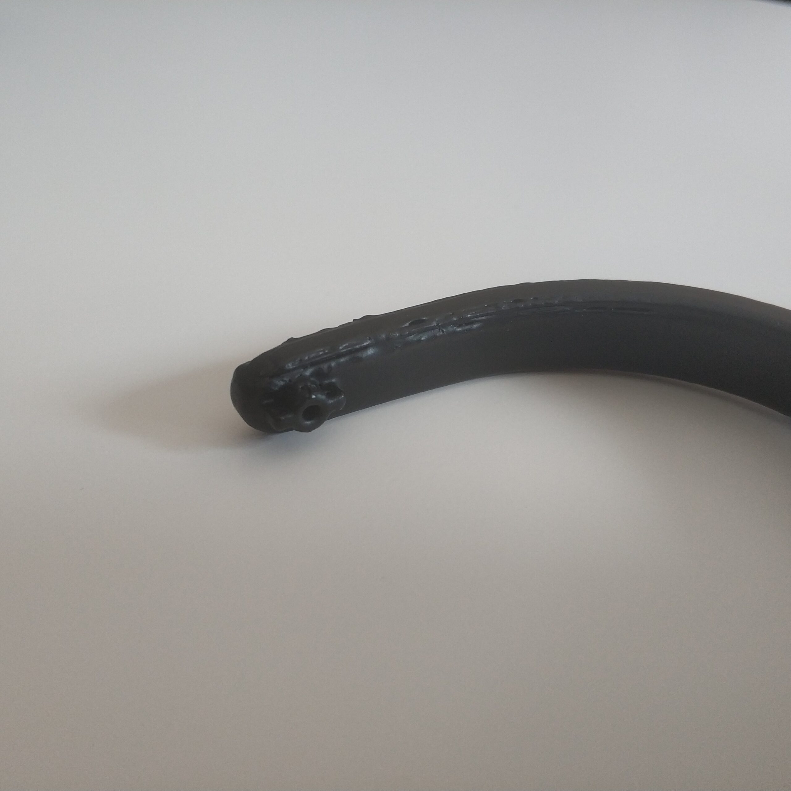
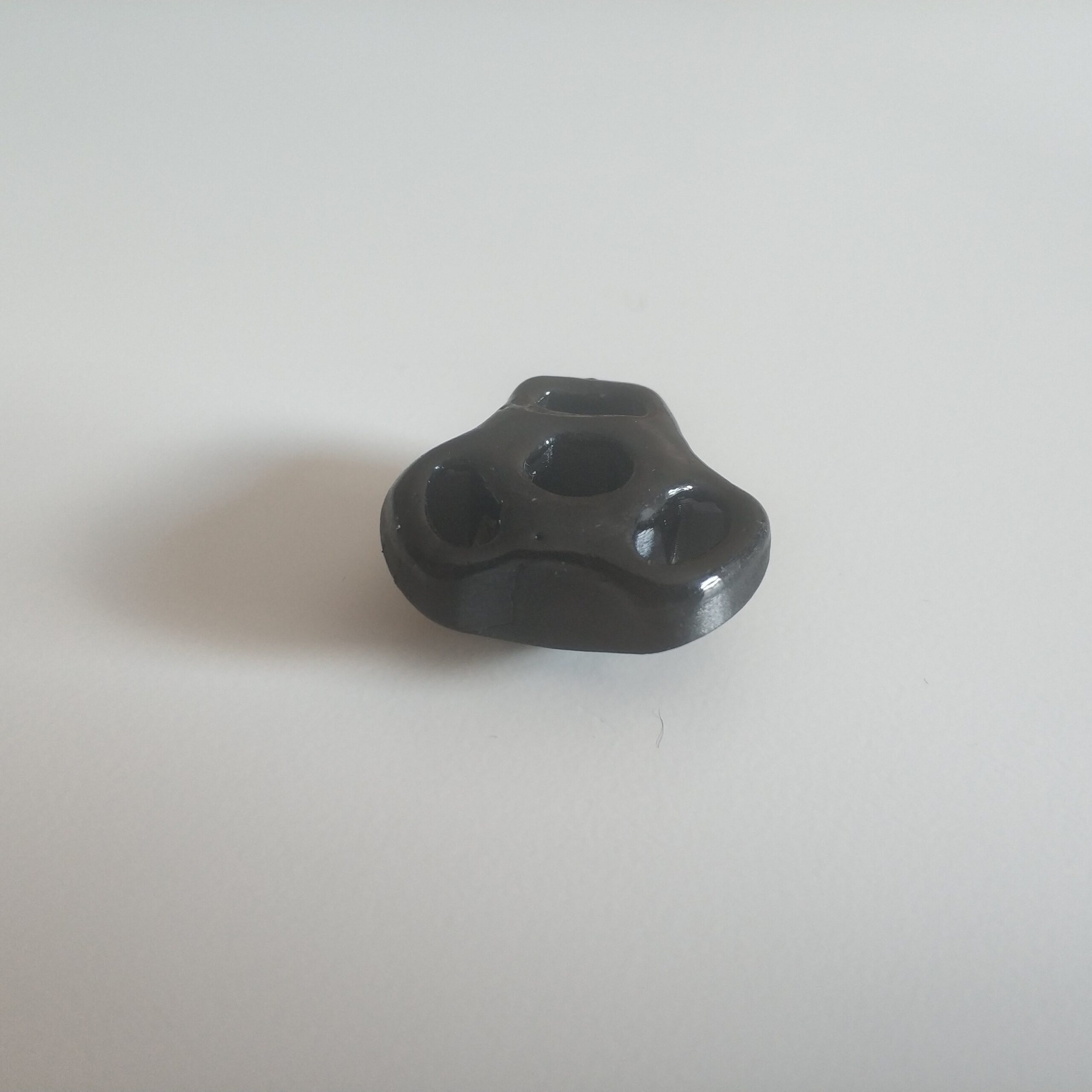
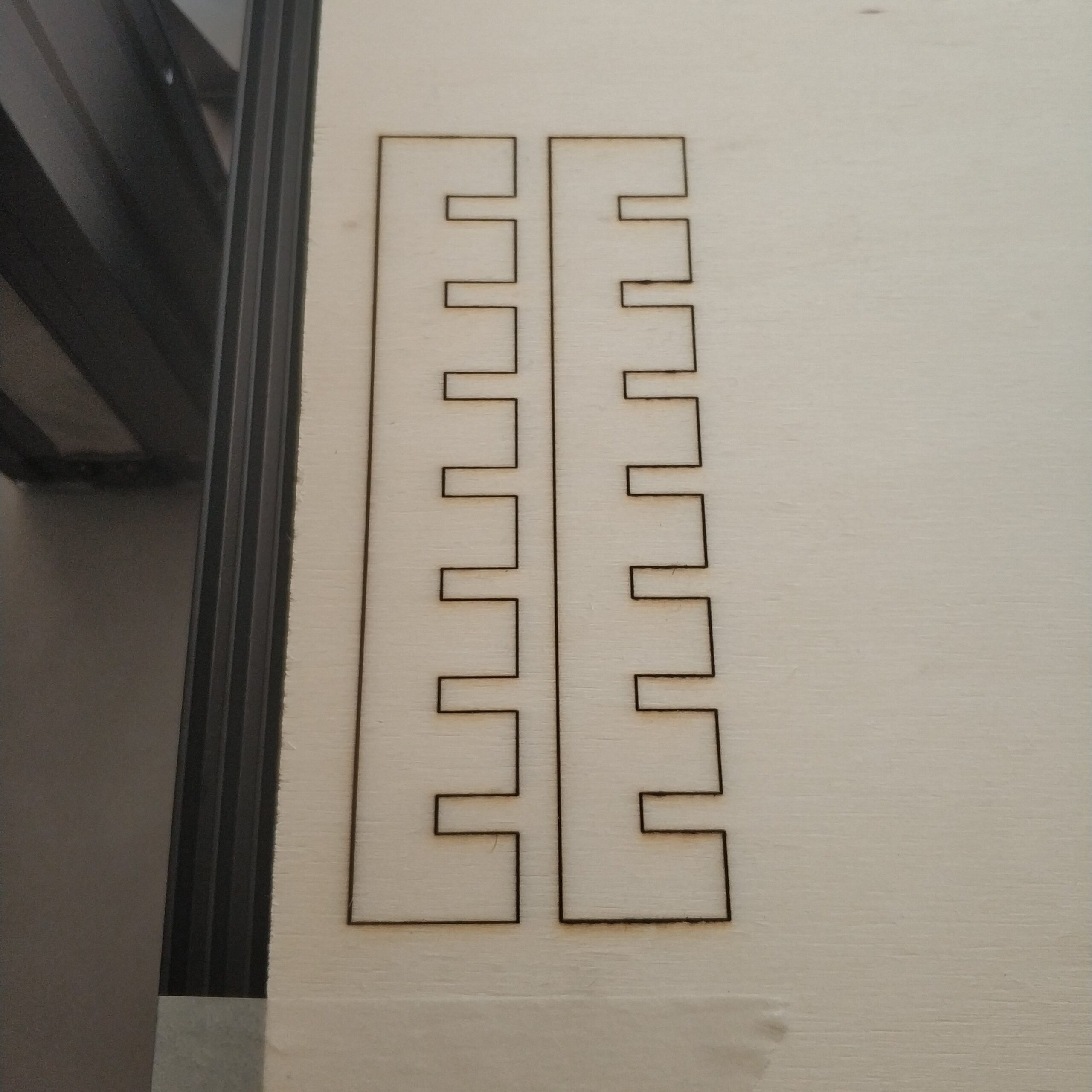
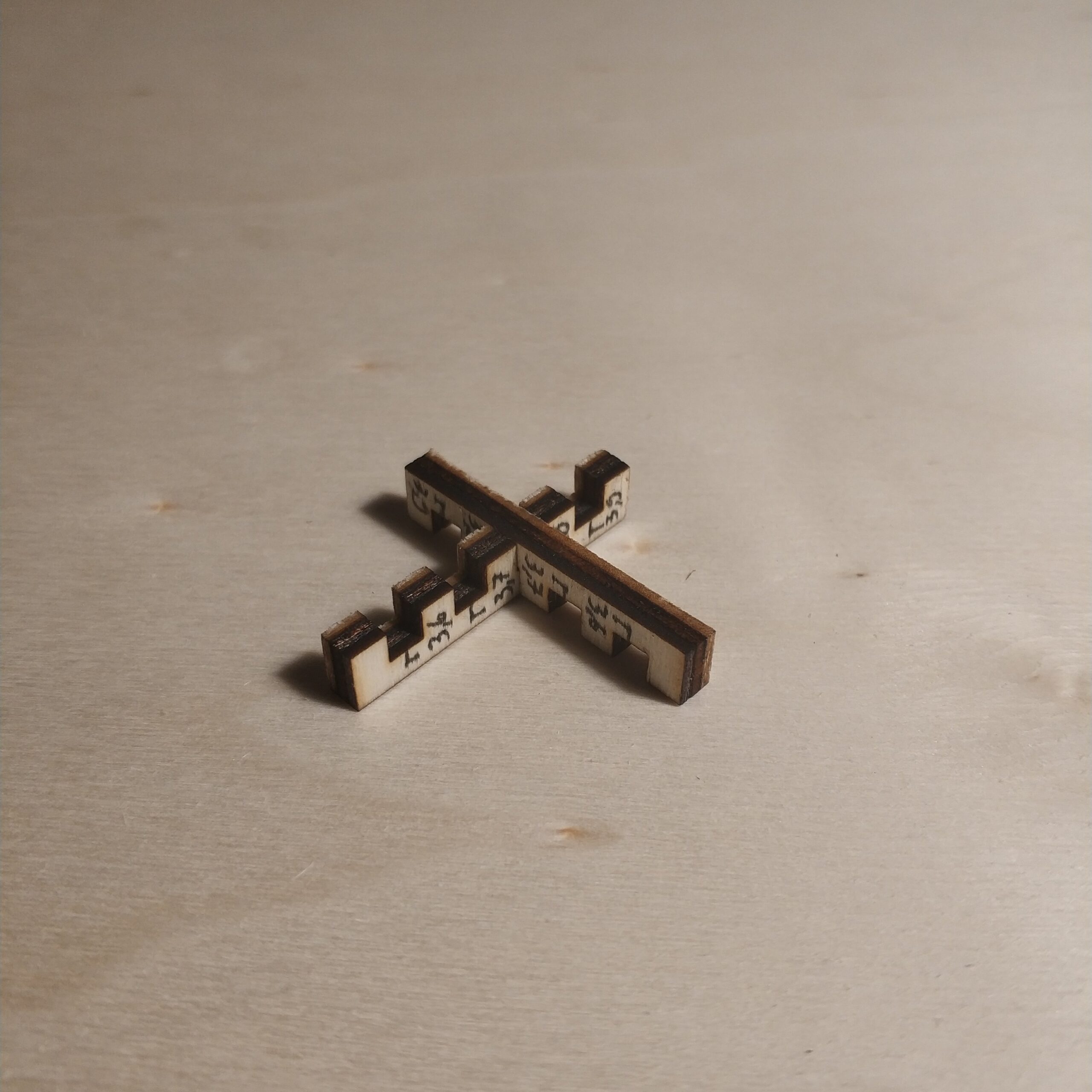
Unfortunately the Schwibbogen only has 11 prongs. That means you would have to install one less LED in a series circuit with the risk that the three LEDs in series would get 4V instead of 3V, which could destroy them or be lazy and hide an LED in the housing. I tried both and broke two LEDs on the first left and right of the middle (see pictures) and then decided on the lazy variant.
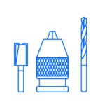
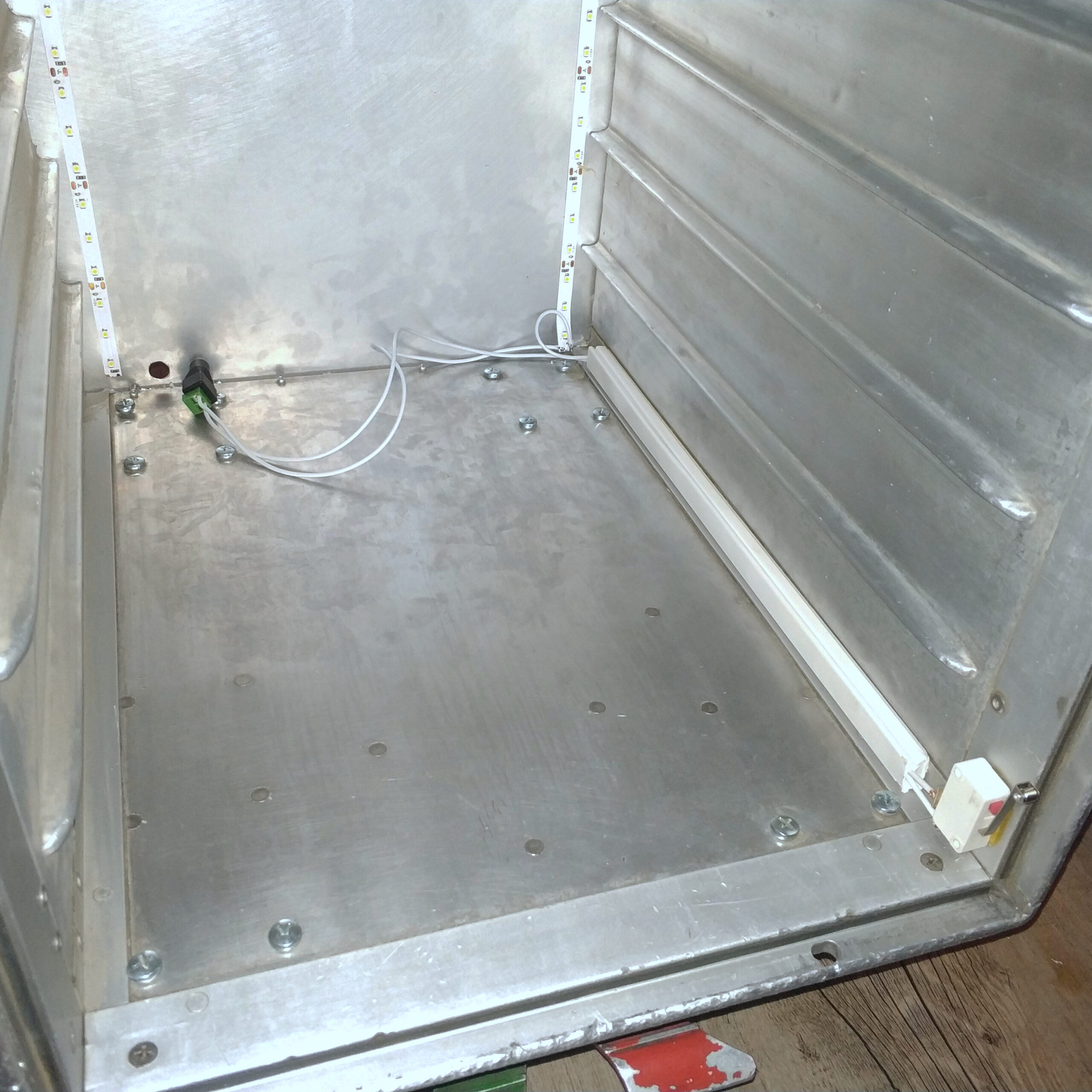
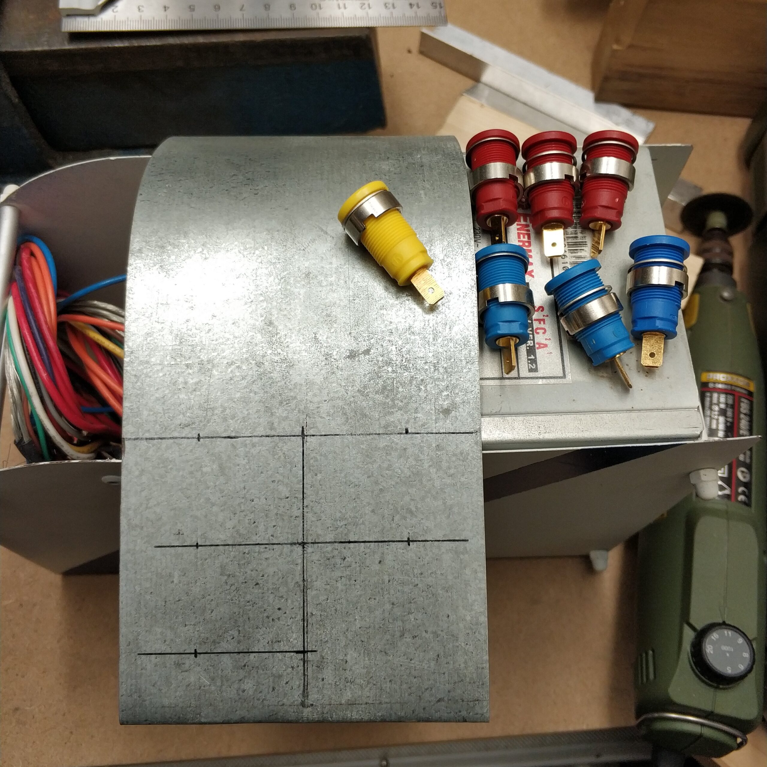
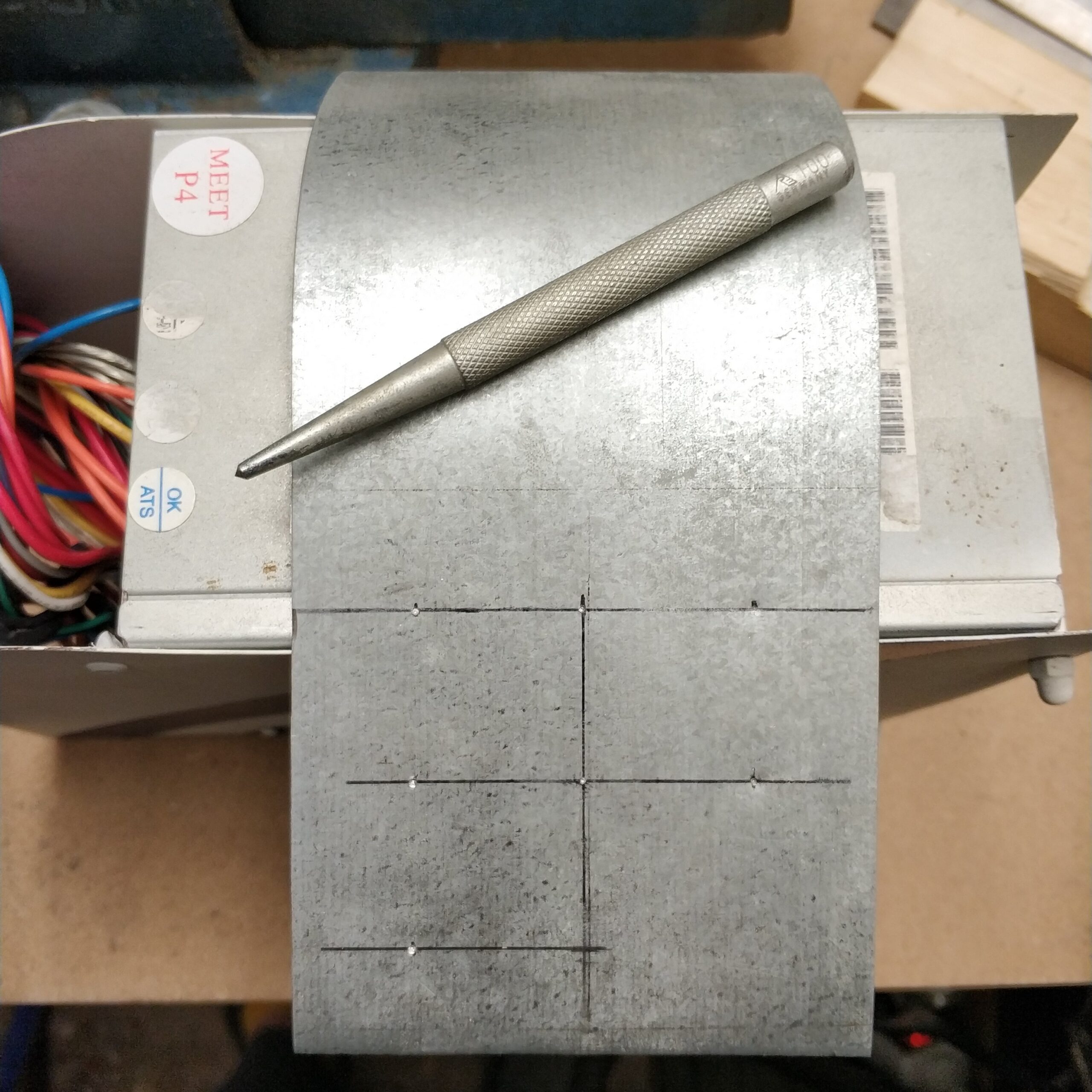
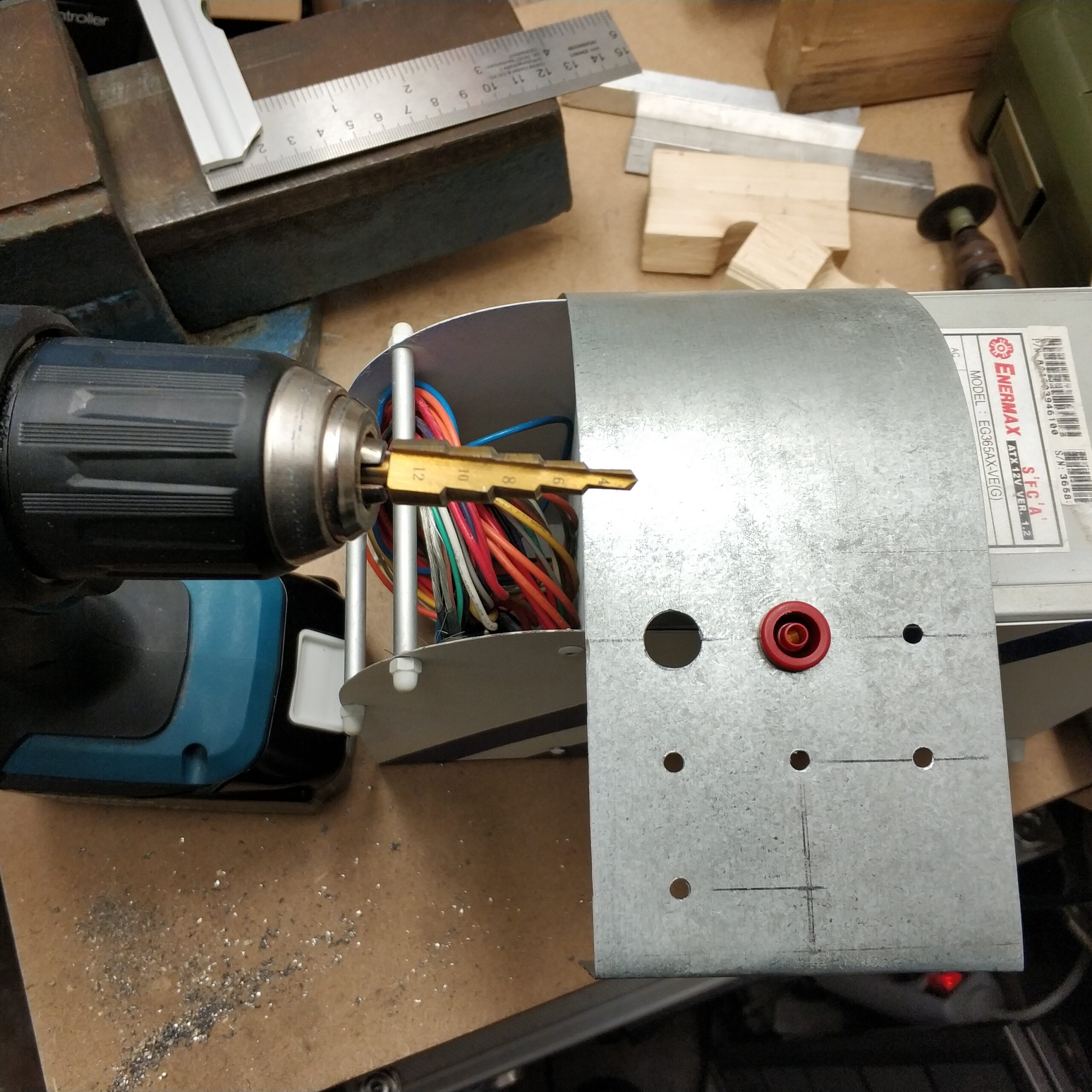
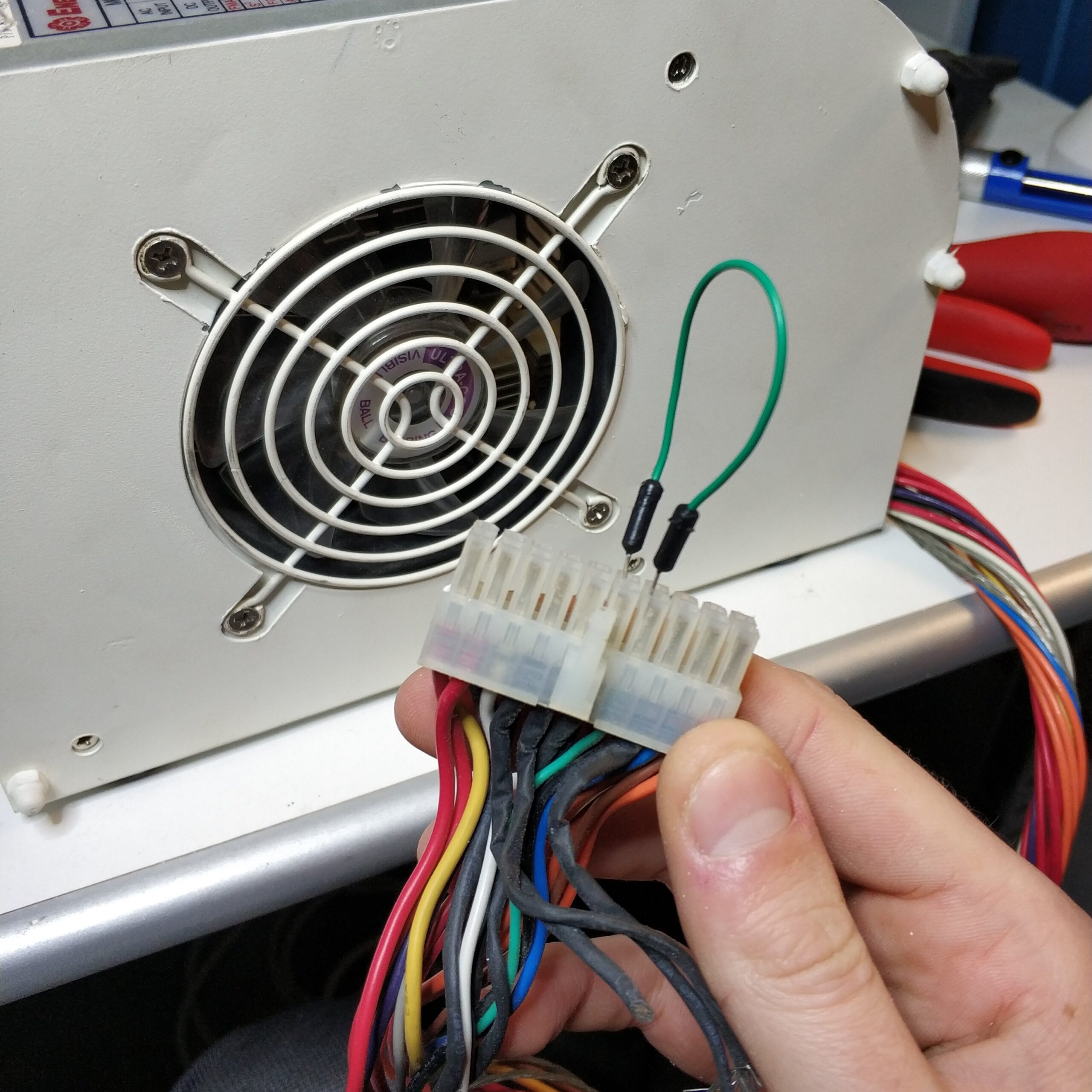
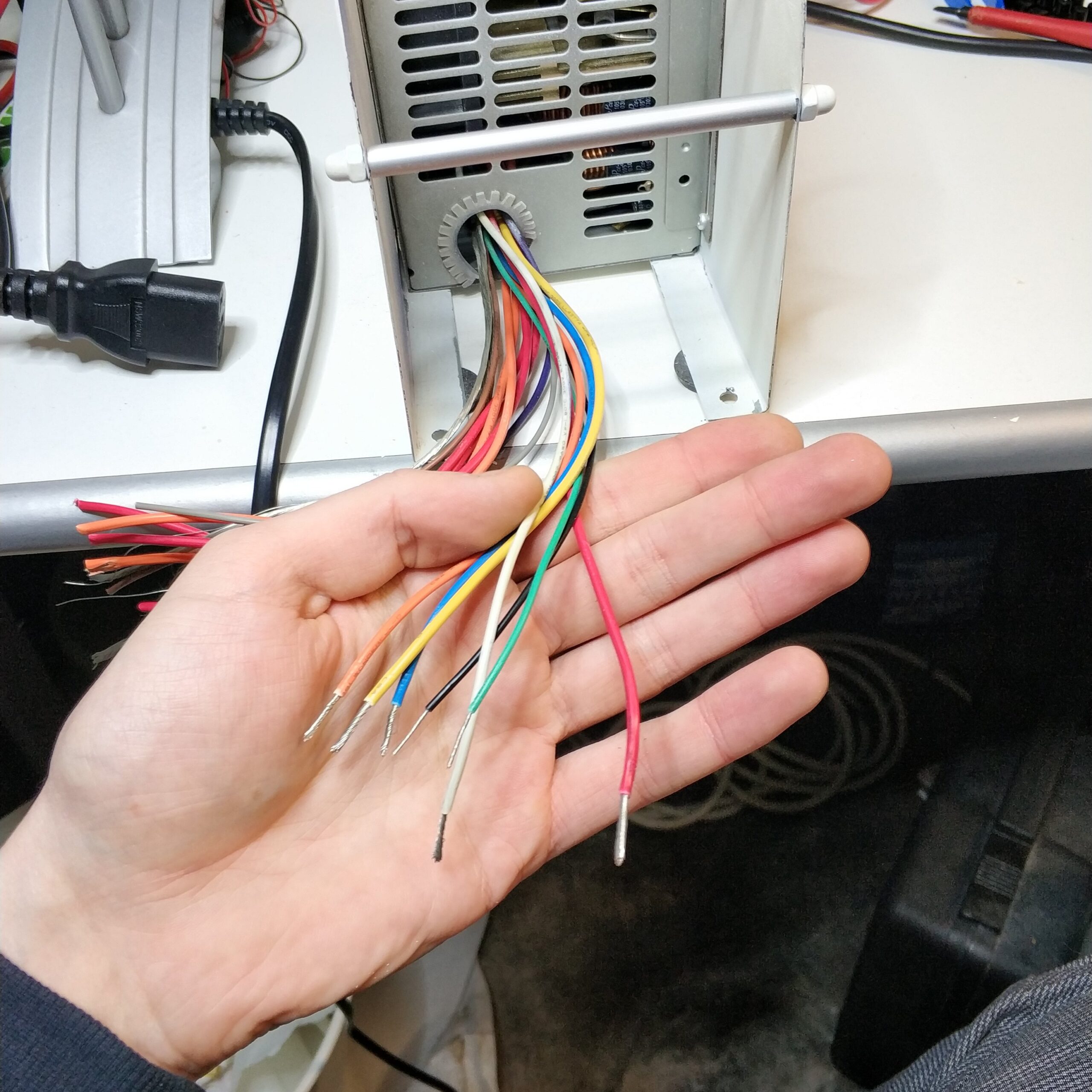
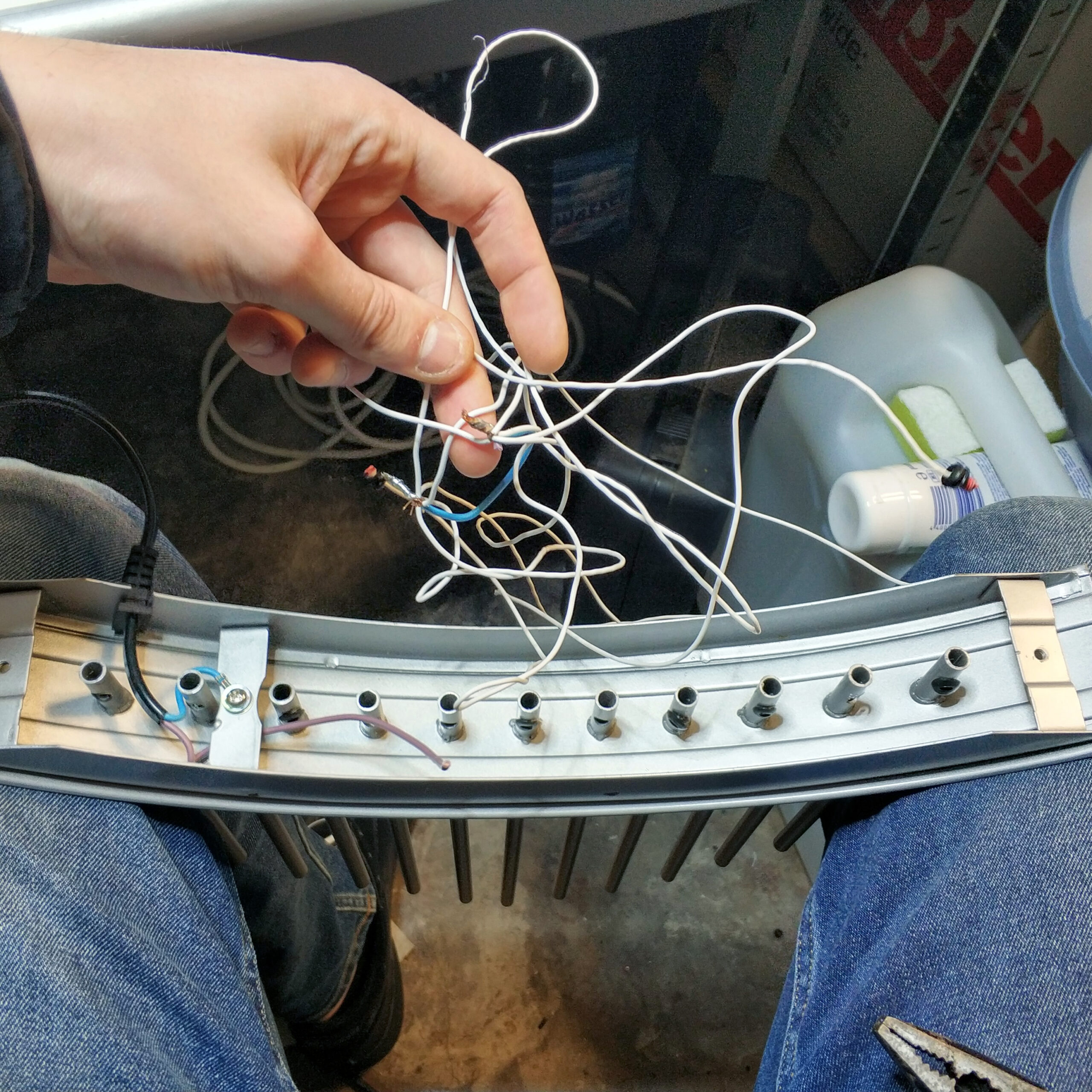
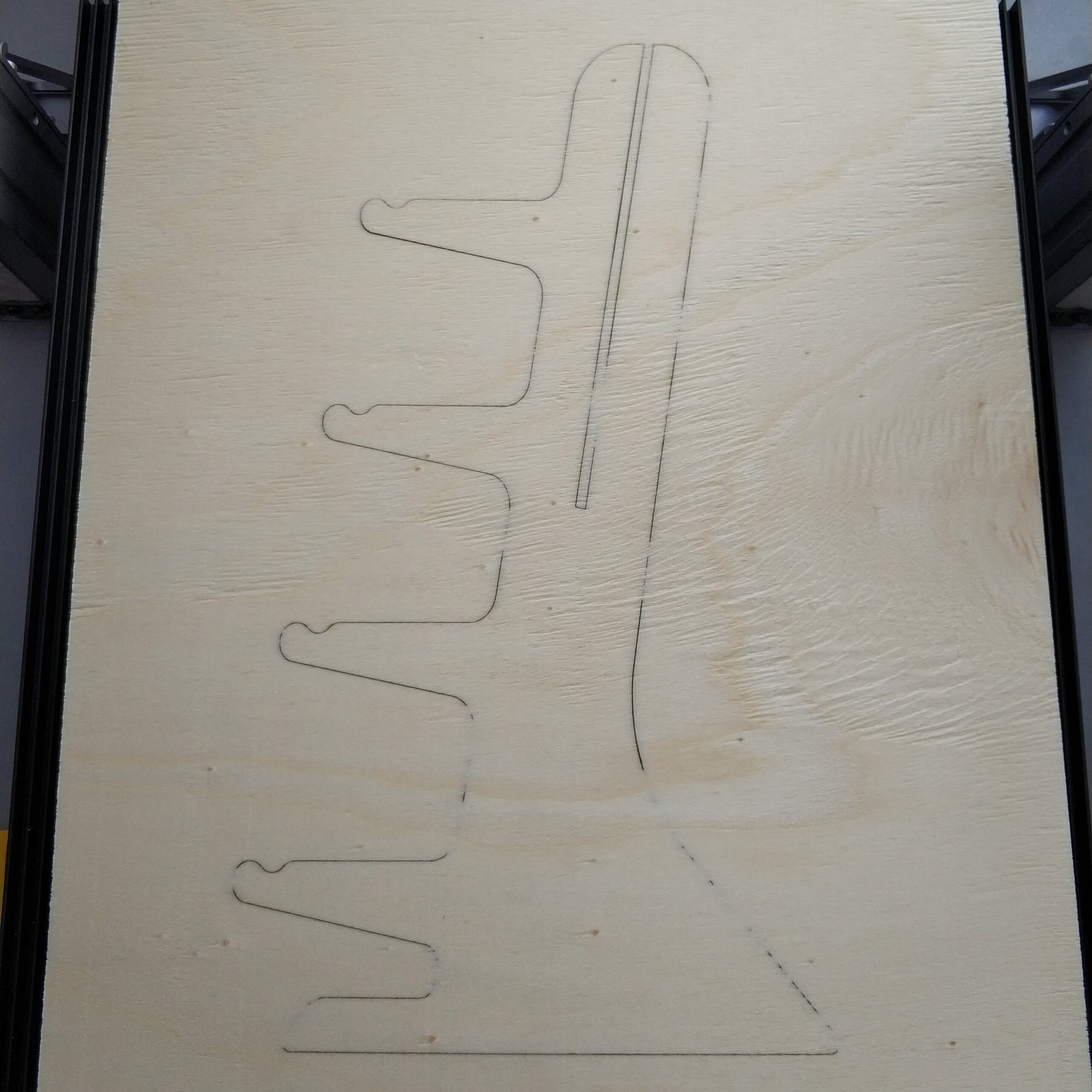
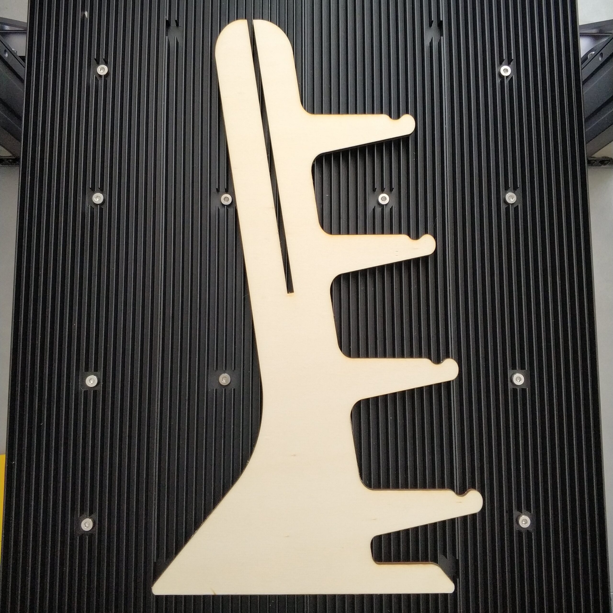
During the implementation, the first thing I had to do was remove the old light bulb sockets with a drill. From below I then pulled out all the old cables, as the metal of the Schwibbogen itself acted as a conductor. So all light bulbs would be connected in parallel via a cable and the metal. But since I have to connect the LEDs in series and in parallel, the old cables were unusable.
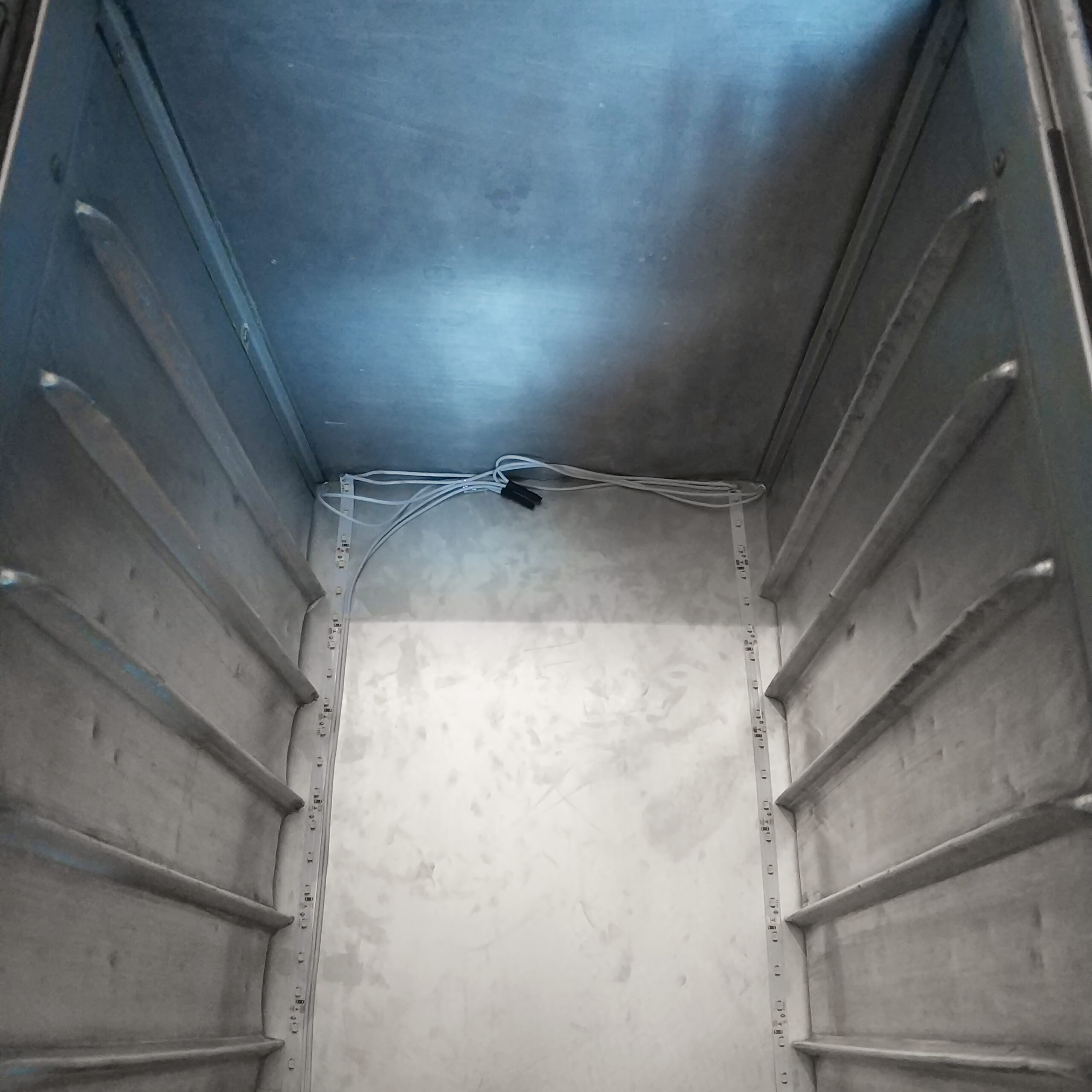
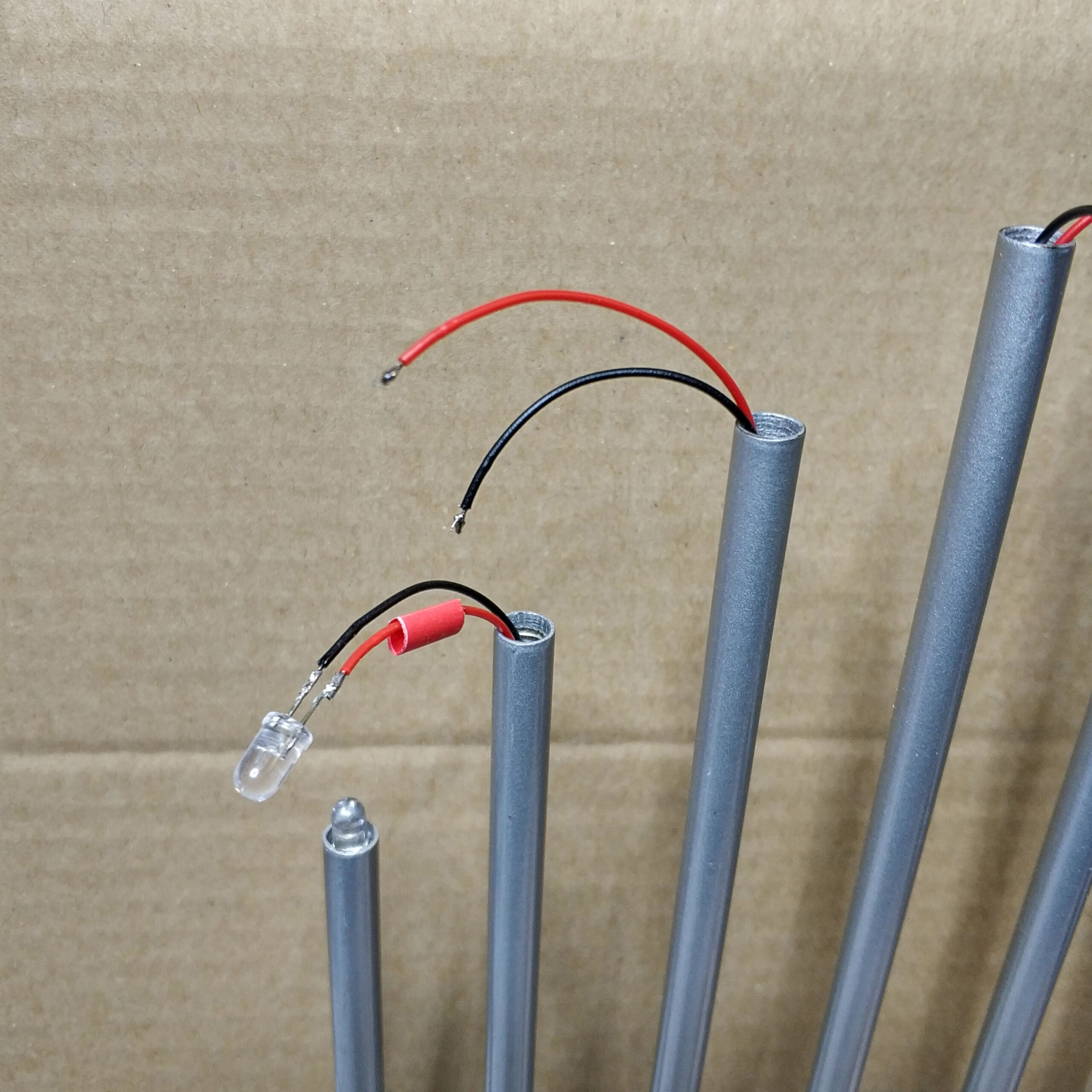
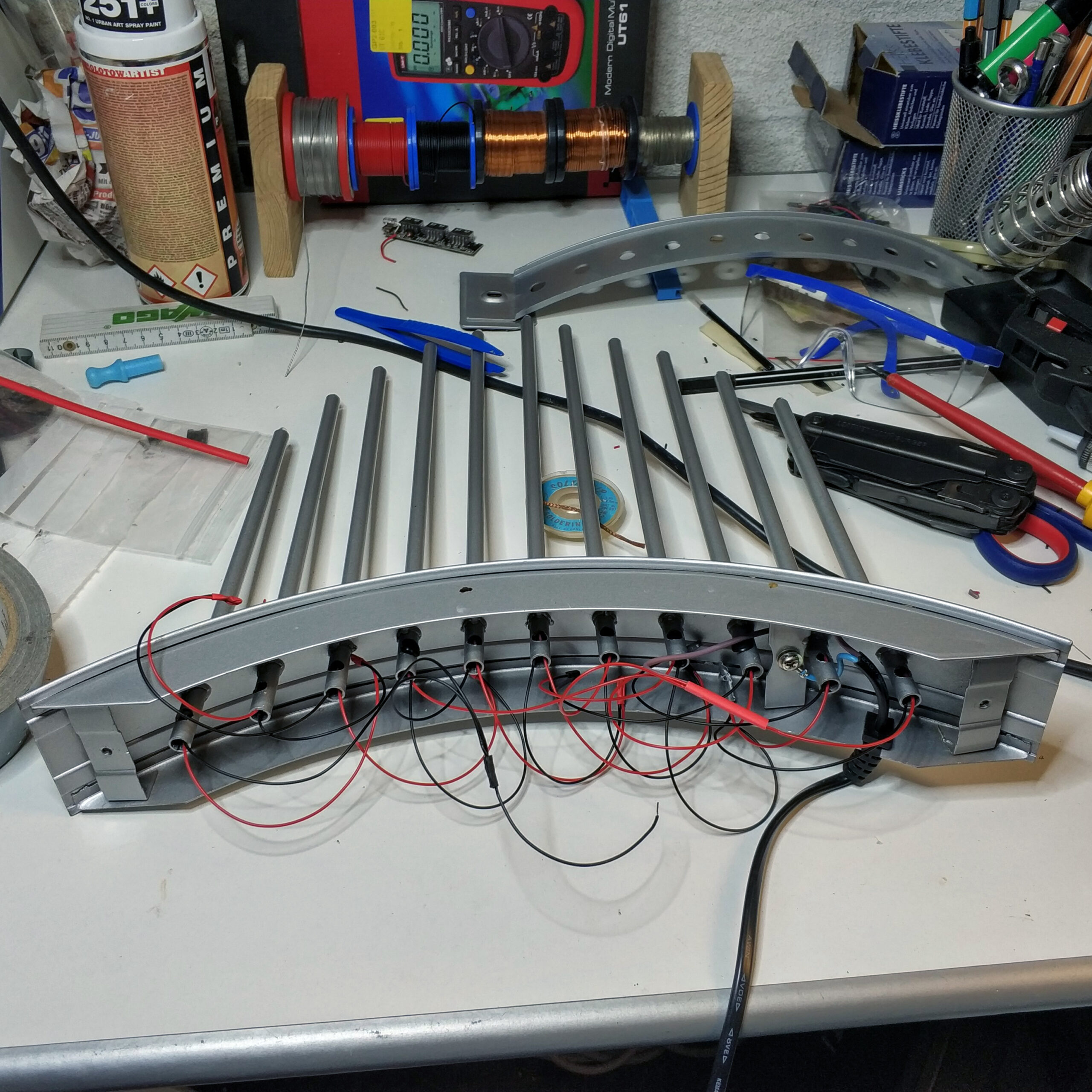
After removing the inside I started pulling cables through the prongs and soldering the LEDs to the ends of the cables. Fortunately, the remains of the lightbulb sockets prevented the LEDs from slipping through and no further gluing was necessary.
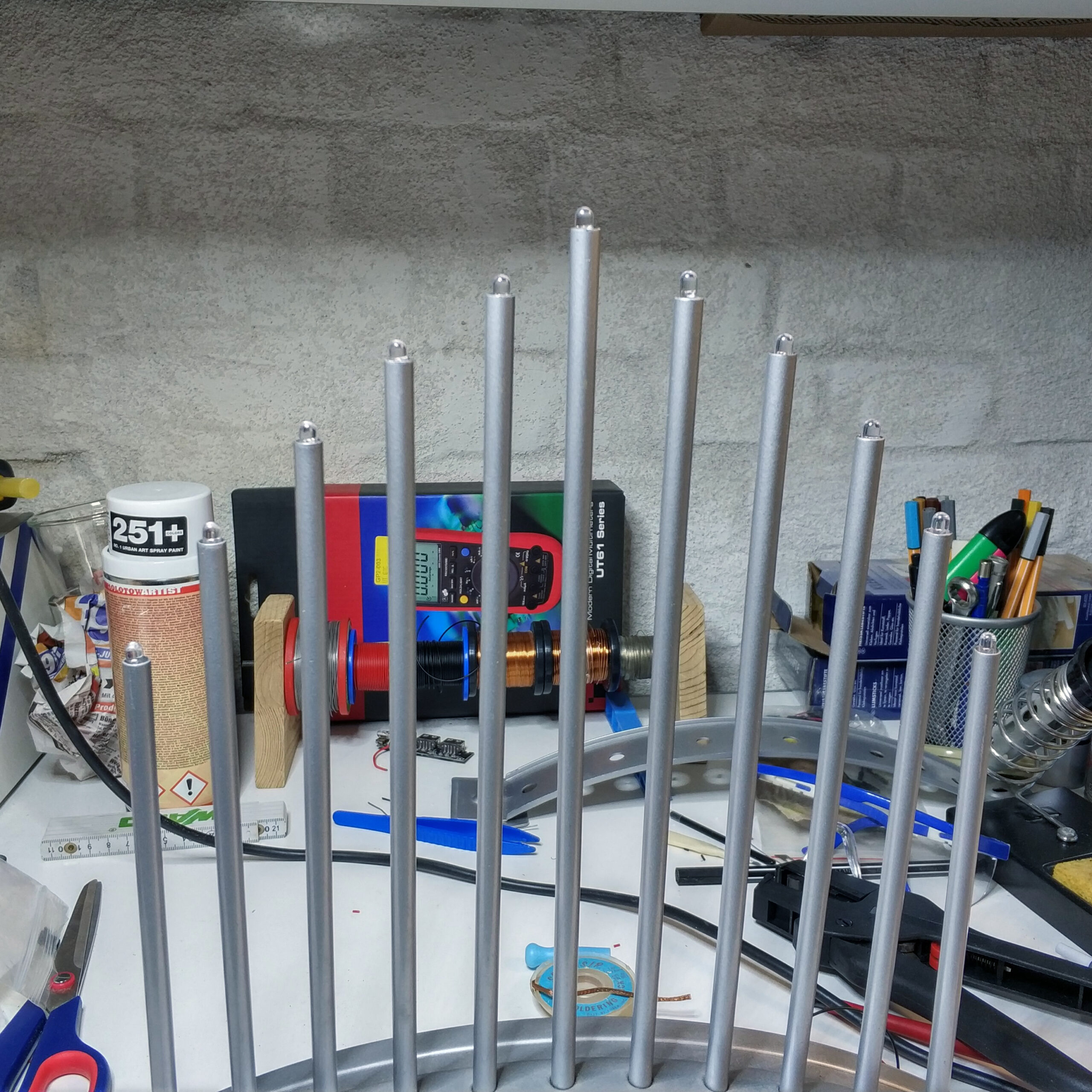
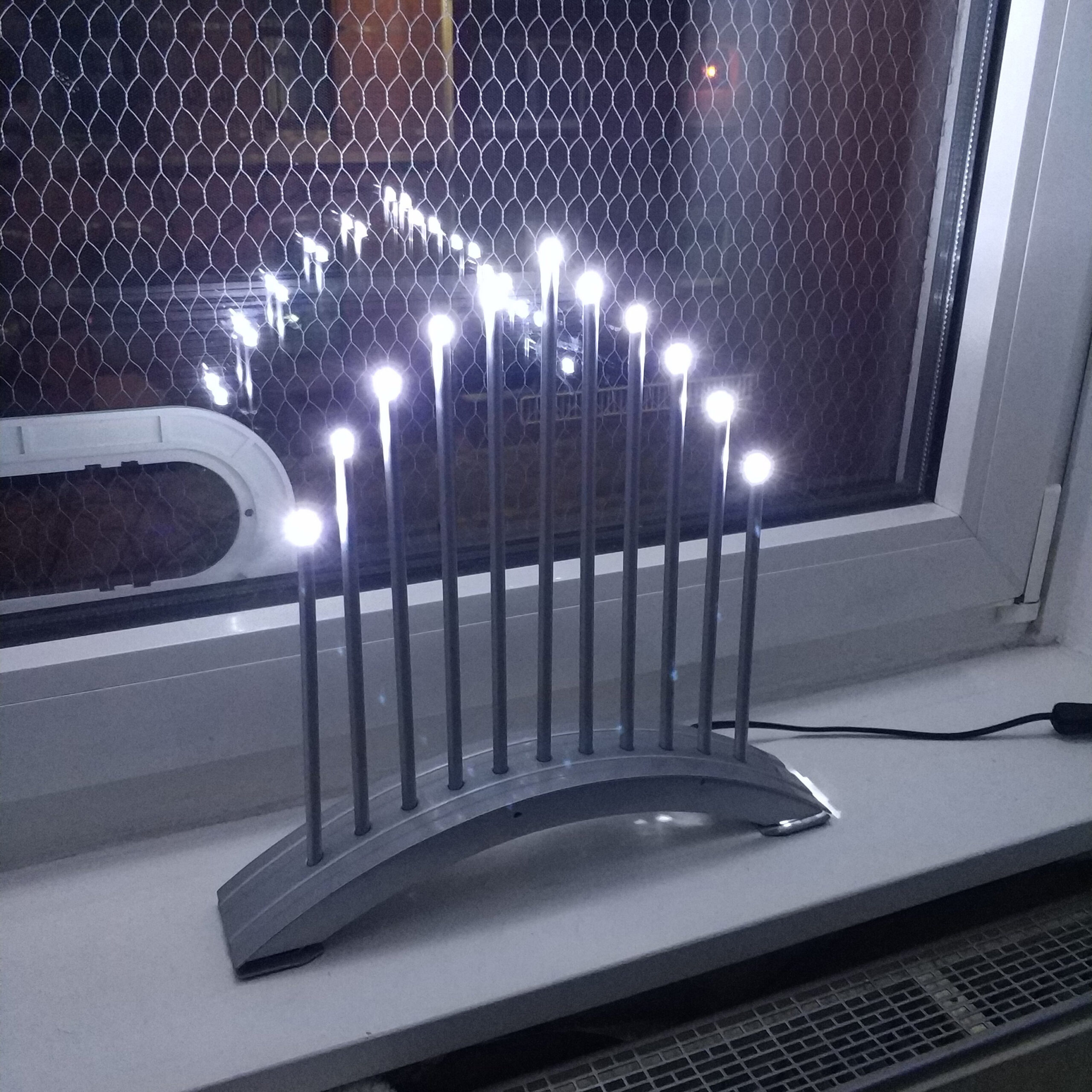
After the first test, almost all LEDs shone equally brightly except for the 3 in the middle. The LEDs to the left and right of the center were darker and later were completely broken. I suspect the 4V mentioned above didn’t do them any good. I don’t know exactly why the middle one remained untouched.
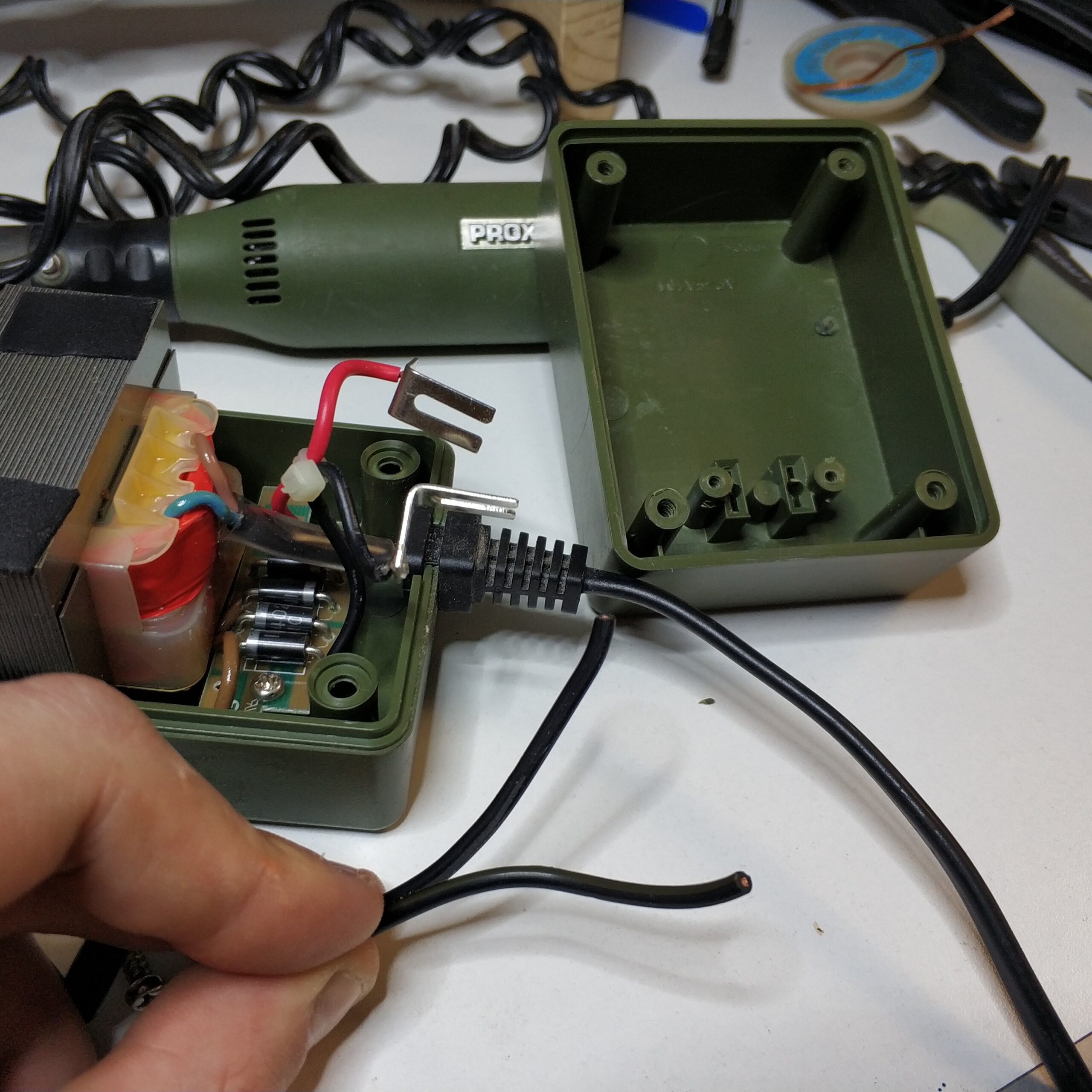
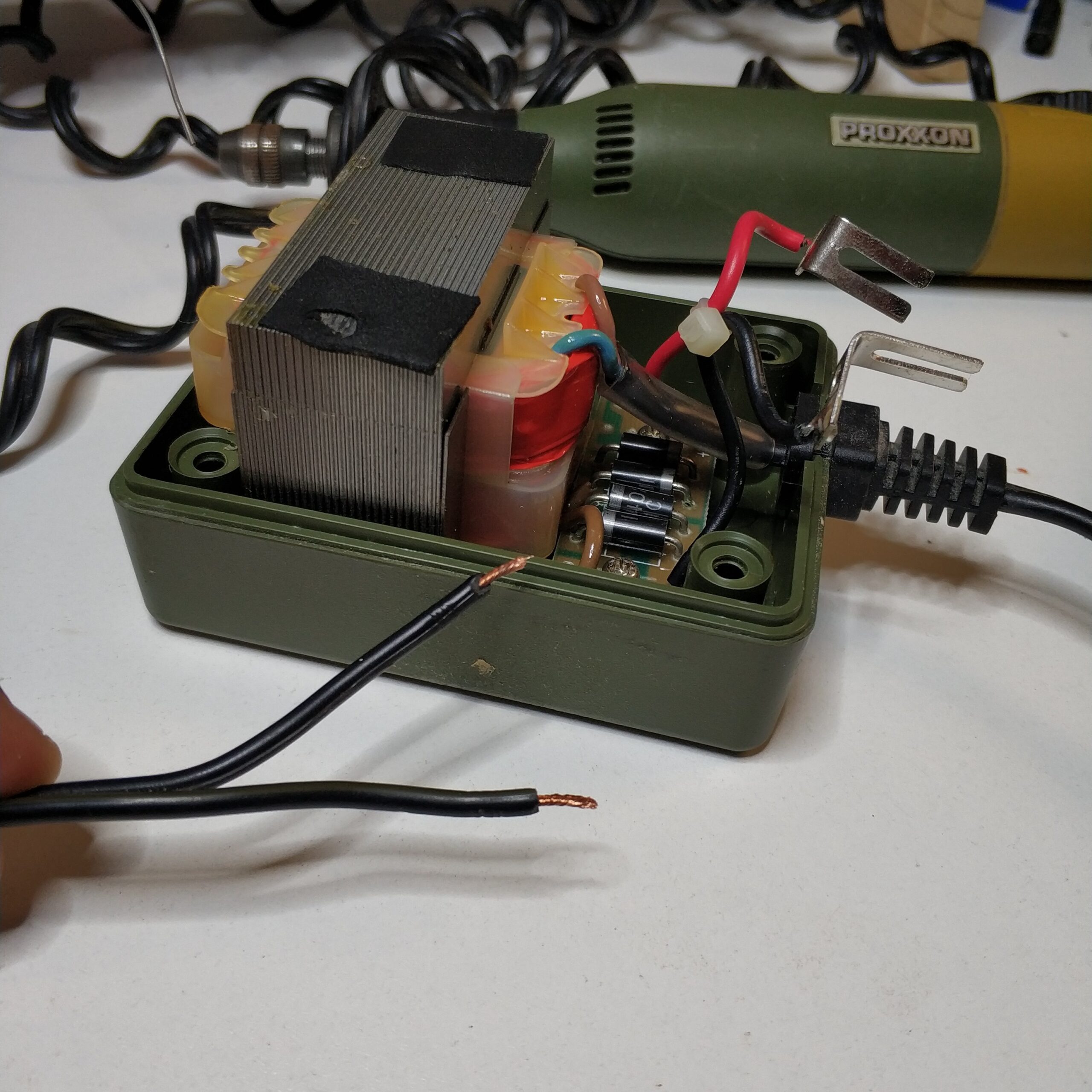
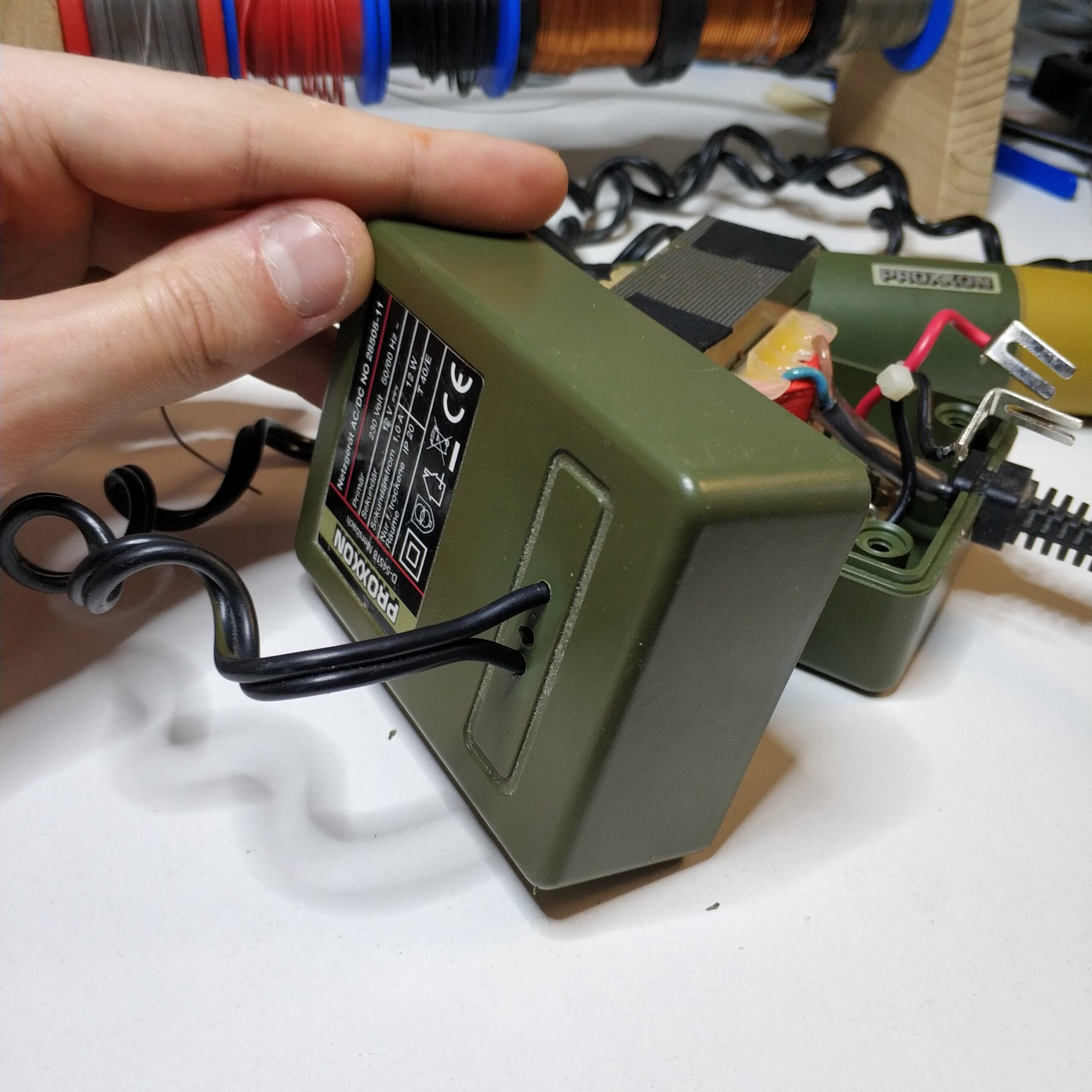
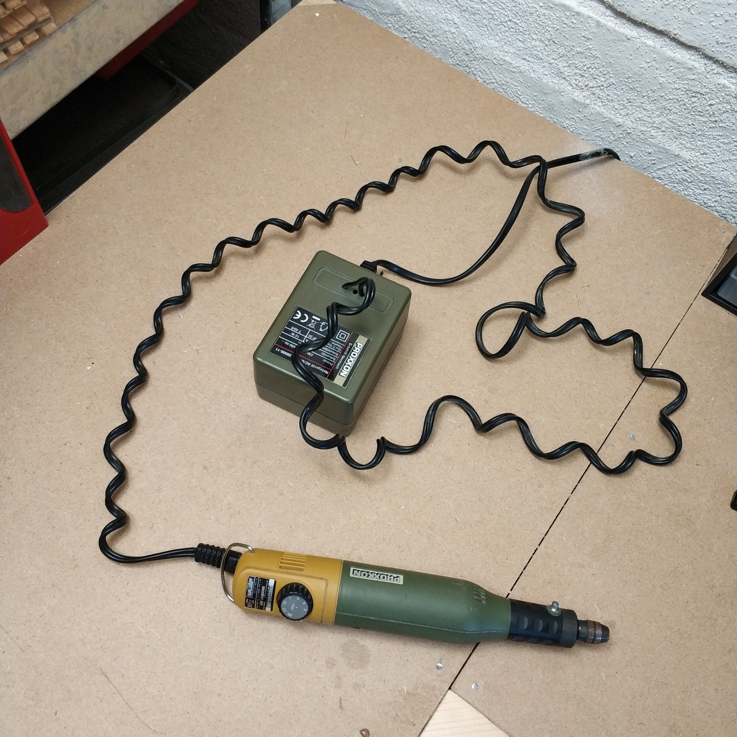
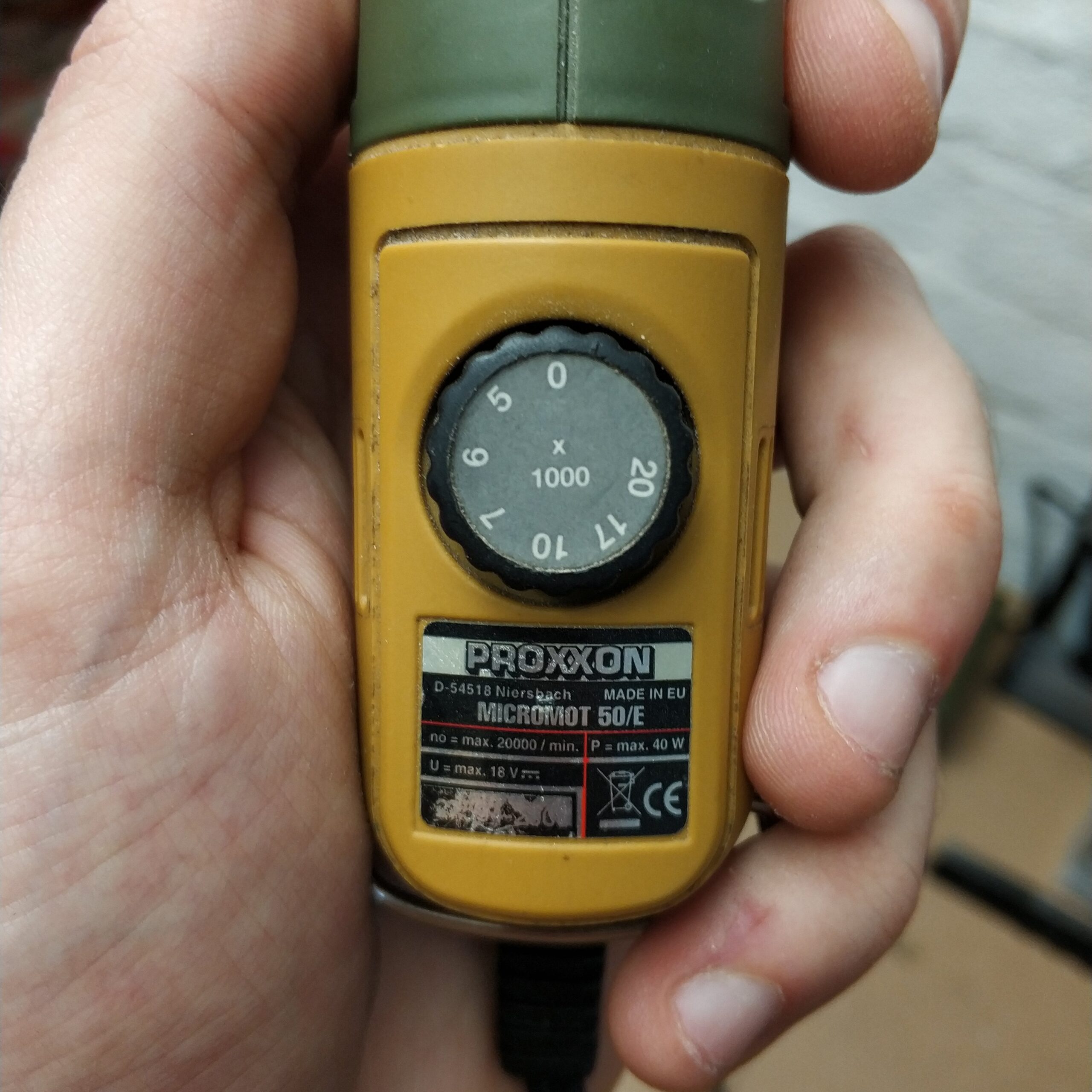
Furthermore, all LEDs flickered, which logically could not be seen in the picture. This is where the acceptance error comes into play. I assumed that the transformer that transforms the 230V to 12V also has a rectifier built in. Also because today practically all small devices are supplied with direct current via switched-mode power supplies, it never occurred to me that the power supply is just a transformer.
I assumed that the flickering was caused by the short voltage drops caused by the rectifier. (see green curve middle voltage curve diagram) Therefore I thought that the problem with a capacitor between the positive and negative pole could be fixed. It actually has this for about 5 seconds until the electrolytic capacitor explodes.
Electrical engineering basic course:
The wrong way of connecting an electrolytic capacitor to a direct current source and in the same sense to an alternating voltage is a death sentence for this type of capacitor.
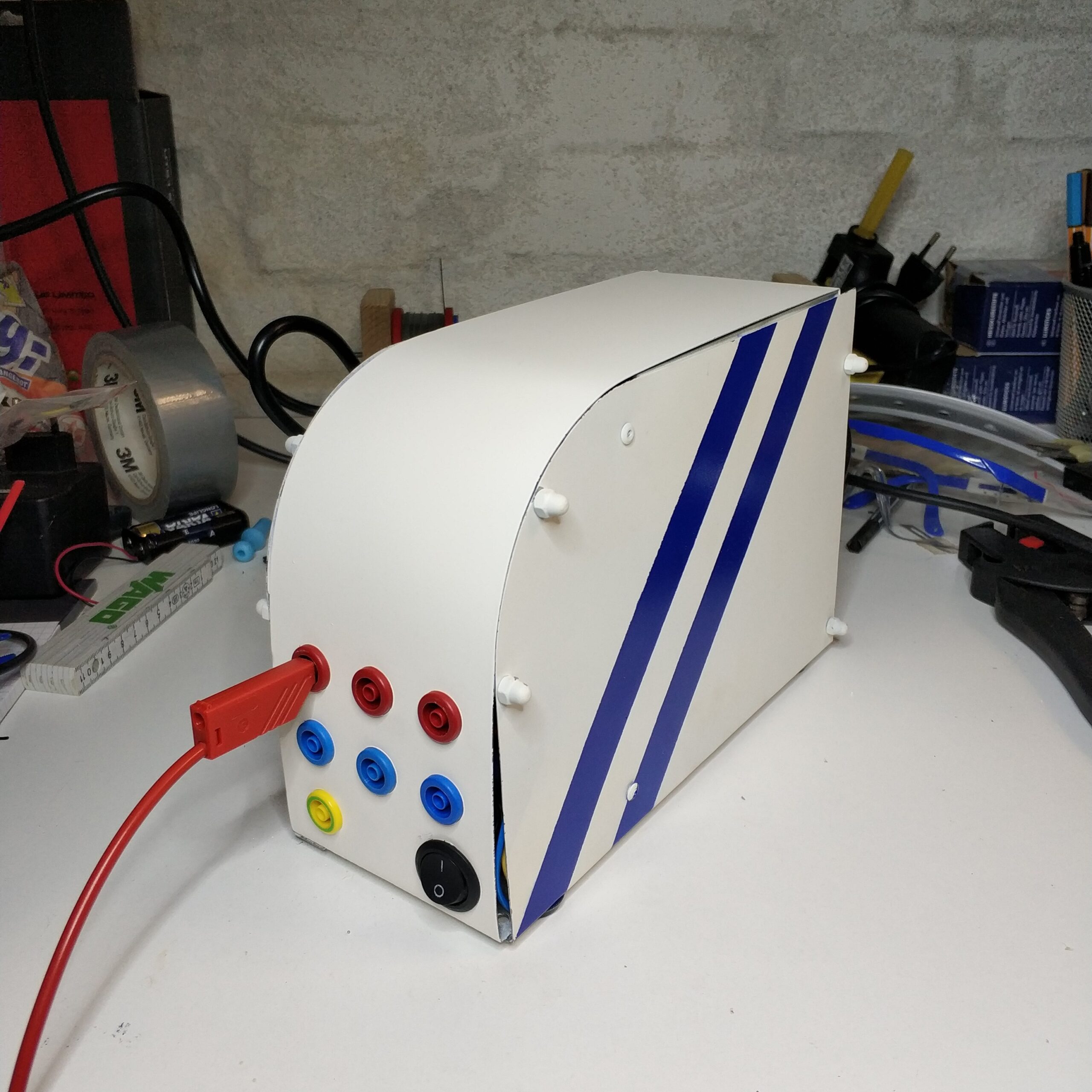
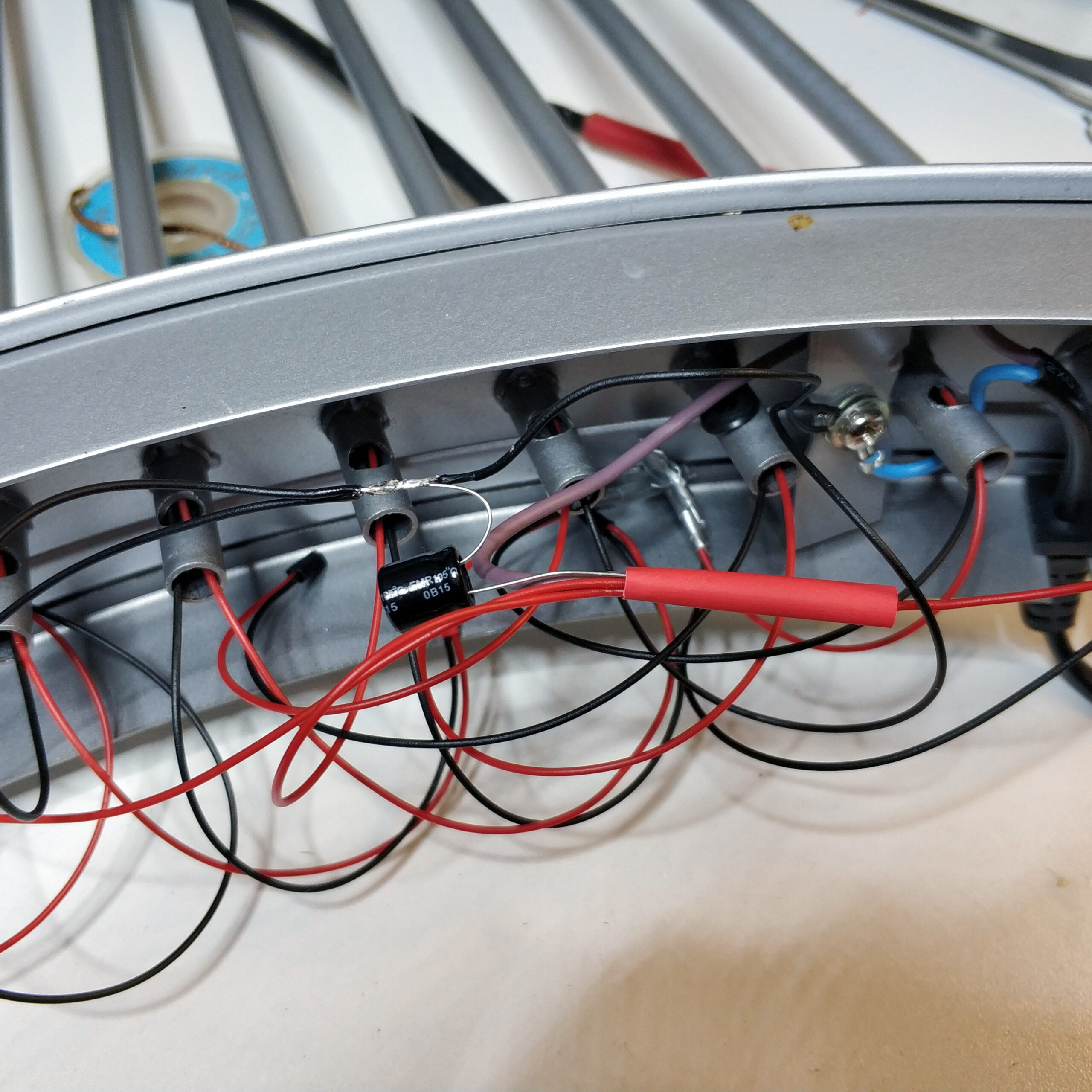
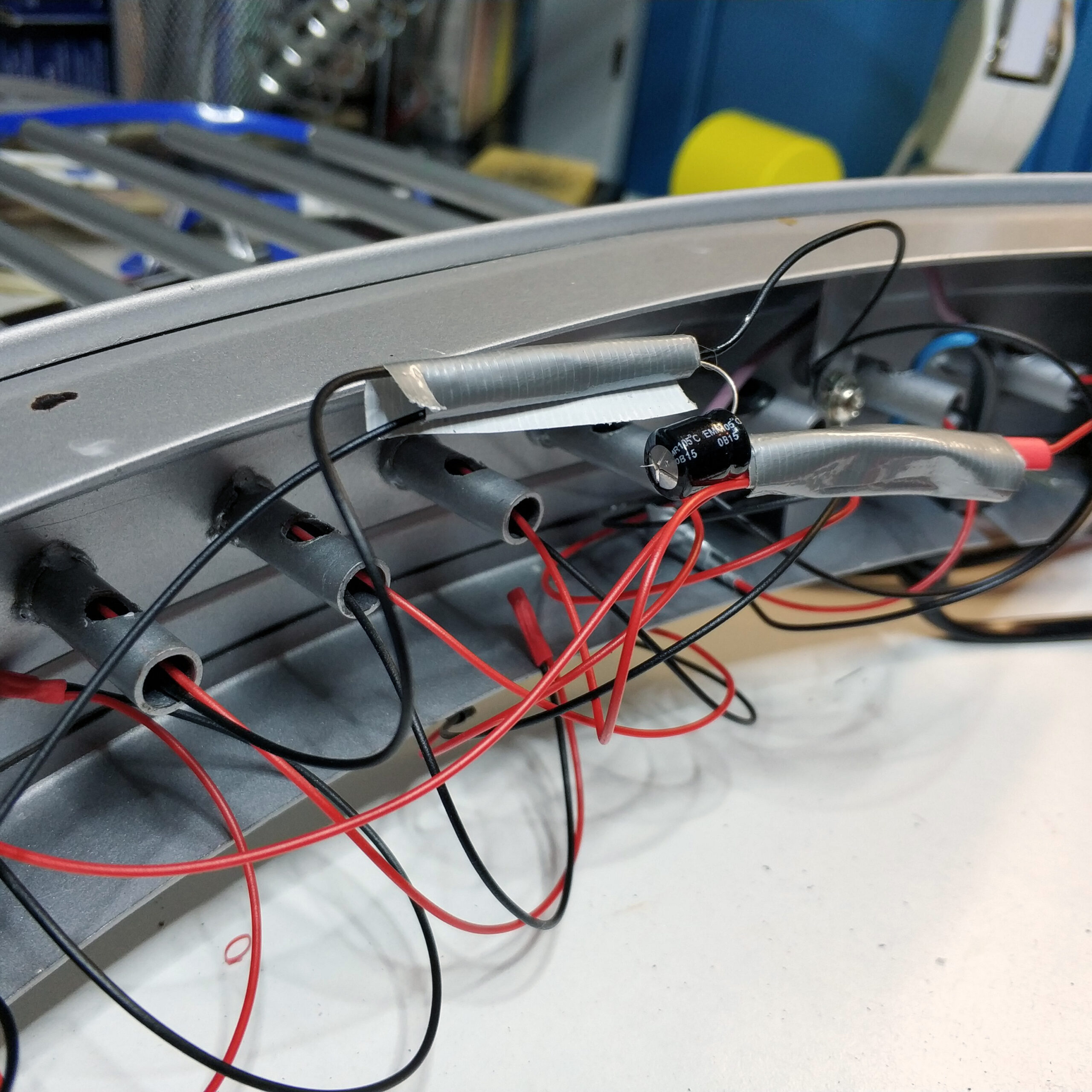
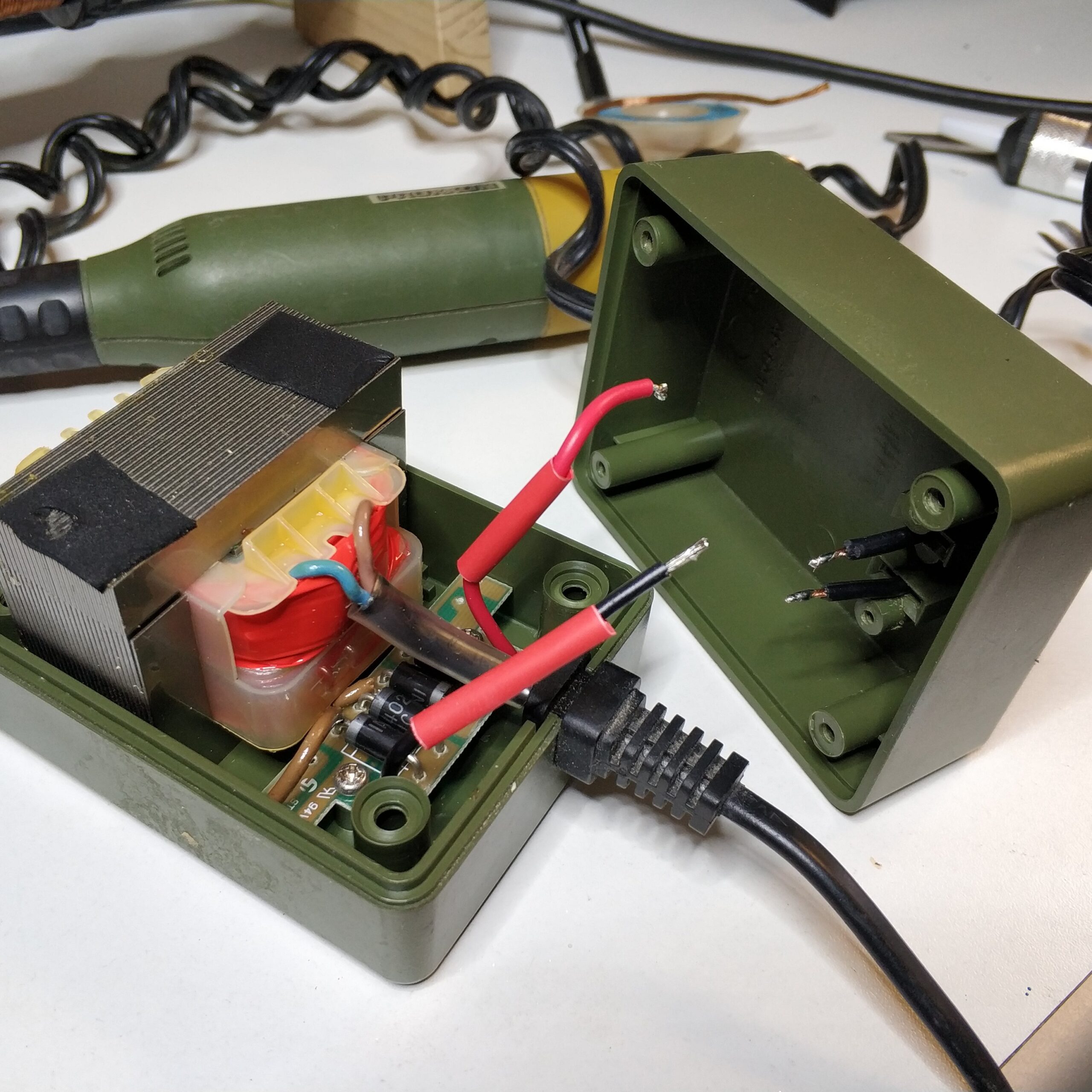
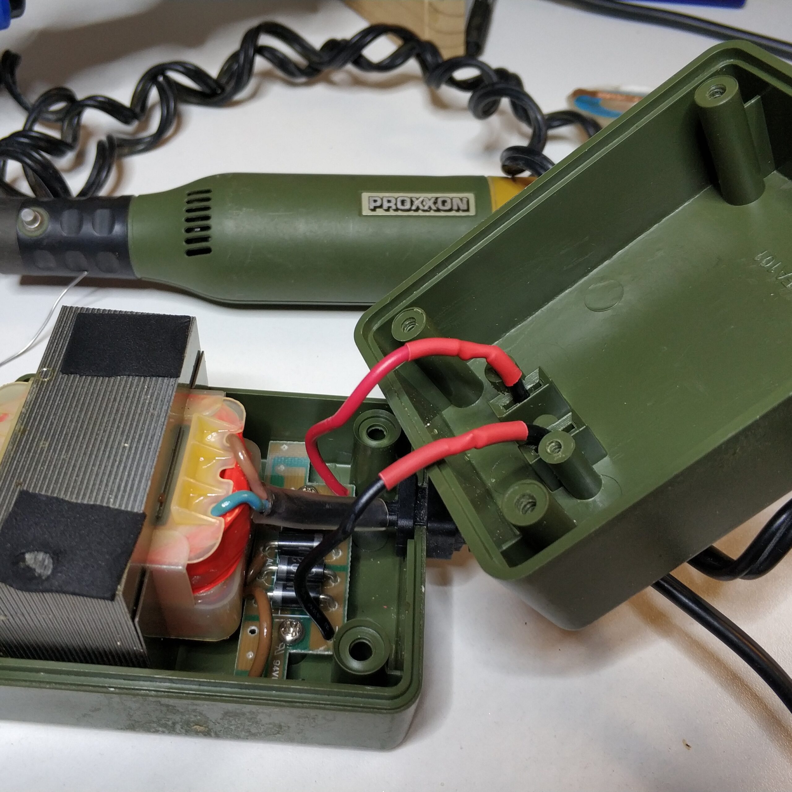
After this electrical engineering refresher experience, it became clear to me that there is 12V AC voltage at the cable outputs. After building the rectifier and rewiring, I had a glowing candle arch.
In the following I would like to go into more detail on the topic with the help of the graphic …